Welding Terms Glossary

Welding Terms Glossary

Abrasive – Slag used for cleaning or surface roughening.

Active Flux – Submerged-arc welding flux from which the amount of elements deposited in the weld metal is dependent upon welding conditions, primarily arc voltage.

Adhesive Bonding – Surfaces, solidifies to produce an adhesive bond.

Air Carbon Arc Cutting – An arc cutting process in which metals to be cut are melted by the heat of carbon arc and the molten metal is removed by a blast of air.

All-Weld-Metal Test Specimen – A test specimen with the reduction section composed wholly of weld metal.

Alloying – Adding a metal or alloy to another metal or alloy.

Alternating Current (AC) – Electric current that reverses direction periodically, usually many times per second.

Annealed Condition – A metal or alloy that has been heated and then cooled to remove internal stresses and to make the material less brittle.

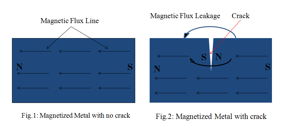
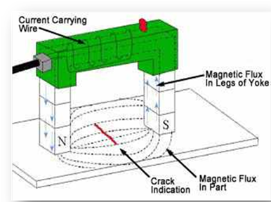
Arc Blow – The deflection of an electric arc from its normal path because of magnetic forces.

Arc Cutting – A group of thermal cutting processes that severs or removes metal by melting with the heat of an arc between an electrode and the work piece.

Arc Force – The axial force developed by an arc plasma.

Arc Gouging – An arc cutting procedure used to form a bevel or groove.

Arc Length – The distance from the tip of the electrode or wire to the work piece.

Arc Time – The time during which an arc is maintained.

Arc Voltage – The voltage across the welding arc.

Arc Welding – A group of welding processes which produces coalescence of metals by heating them with an arc, with or without the application of pressure and with or without the use of filler metal.

Arc Welding Deposition Efficiency (%) – The ratio of the weight of filler metal deposited to the weight of filler metal melted.

Arc Welding Electrode – A part of the welding system through which current is conducted that ends at the arc.

As-Welded – The condition of the weld metal, after completion of welding, and prior to any subsequent thermal or mechanical treatment.

Atomic Hydrogen Welding – An arc welding process which produces coalescence of metals by heating them with an electric arc maintained between two metal electrodes in an atmosphere of hydrogen.

Austenitic – Composed mainly of gamma iron with carbon in solution.

Autogenous Weld – A fusion weld made without the addition of filler metal.

Automatic – The control of a process with equipment that requires little or no observation of the welding and no manual adjustment of the equipment controls.

Back Gouging – The removal of weld metal and base metal from the other side of a partially welded joint to assure complete penetration upon subsequent welding from that side.

Backfire – The momentary recession of the flame into the welding or cutting tip followed by reappearance or complete extinction of the flame.

Backhand Welding – A welding technique where the welding torch or gun is directed opposite to the direction of welding.

Backing – A material (base metal, weld metal, or granular material) placed at the root of a weld joint for the purpose of supporting molten weld metal.

Backing Gas – A shielding gas used on the underside of a weld bead to protect it from atmospheric contamination.

Backing Ring – Backing in the form of a ring, generally used in the welding of pipe.

Back-Step Sequence – A longitudinal sequence in which the weld bead increments are deposited in the direction opposite to the progress of welding the joint.

Base Metal (material) – The metal (material) to be welded, brazed, soldered, or cut. See also substrate.

Bend Radius – Radius of curvature on a bend specimen or bent area of a formed part. Measured on the inside of a bend.

Bevel – An angled edge preparation.

Blanking – Process of cutting material to size for more manageable processing.

Braze Welding – A method of welding by using a filler metal, having a liquidus above 840 °F (450 °C) and below the solidus of the base metals.

Brazing – A group of welding processes which produces coalescence of materials by heating them to a suitable temperature and by using a filler metal, having a liquidus above 840 °F (450 °C) and below the solidus of the base materials. The filler metal is distributed between the closely fitted surfaces of the joint by capillary attraction.

Burr – A rough ridge, edge, protuberance, or area left on metal after cutting, drilling, punching, or stamping.

Buttering – A form of surfacing in which one or more layers of weld metal are deposited (for example, a high alloy weld deposit on steel base metal which is to be welded to a dissimilar base metal). The buttering provides a suitable transition weld deposit for subsequent completion of the butt weld on the groove face of one member.

Butt Joint – A joint between two members lying in the same plane.

Camber – Deviation from edge straightness, usually the greatest deviation of side edge from a straight line.

Cap Pass – The final pass of a weld joint.

Carrier Gas – In thermal spraying, the gas used to carry powdered materials from the powder feeder or hopper to the gun.

Capillary Action – The action by which the liquid surface is elevated or depressed where it contacts a solid because the liquid molecules are attracted to one another and to the solid molecules.

Cladding – A thin (> 0.04″) layer of material applied to the base material to improve corrosion or wear resistance of the part.

Clad Metal – A composite metal containing two or three layers that have been welded together. The welding may have been accomplished by roll welding, arc welding, casting, heavy chemical deposition, or heavy electroplating.

Coalescence – The uniting of many materials into one body.

Coherent – Moving in unison.

Cold Lap – Incomplete fusion or overlap.

Collimate – To render parallels to a certain line or direction.

Complete Fusion – Fusion that has occurred over the entire base material surfaces intended for welding, and between all layer and passes.

Complete Joint Penetration – Joint penetration in which the weld metal completely fills the groove and is fused to the base metal throughout its total thickness.

Constant Current Power Source – An arc welding power source with a volt-ampere output characteristic that produces a small welding current change from a large arc voltage change.

Constant Voltage Power Source – An arc welding power source with a volt-ampere output characteristic that produces a large welding current change from a small arc voltage change.

Contact Tube – A system component that transfers current from the torch gun to a continuous electrode.

Contact Resistance – The resistance in ohms between the contacts of a relay, switch, or other device when the contacts are touching each other.

Contact Tube – A device which transfers current to a continuous electrode

Covered Electrode – A filler metal electrode used in shielded metal-arc welding, consisting of a metal-wire core with a flux covering.

Crater – In arc welding, a depression on the surface of a weld bead.

Crater Crack – A crack in the crater of a weld bead.

Cryogenic – Refers to low temperatures, usually -200 o (-130 o) or below.

Cutting Attachment – A device for converting an oxy-fuel gas-welding torch into an oxy-fuel cutting torch.

Cylinder – A portable container used for transportation and storage of a compressed gas.

Defect – A discontinuity or discontinuities that by nature or accumulated effect (for example, total crack length) renders a part or product unable to meet minimum applicable acceptance standards or specifications.

Density – The ratio of the weight of a substance per unit volume; e.g. mass of a solid, liquid, or gas per unit volume at a specific temperature.

Deposited Metal – Filler metal that has been added during welding, brazing or soldering.

Deposition Efficiency – In arc welding, the ratio of the weight of deposited metal to the net weight of filler metal consumed, exclusive of stubs.

Deposition Rate – The weight of material deposited in a unit of time. It is usually expressed as pounds/hour (lb/h) or kilograms per hour (kg/h).

Depth of Fusion – The distance that fusion extends into the base metal or previous pass from the surface melted during welding.

Dew Point – The temperature and pressure at which the liquefaction of a vapor begins. Usually applied to condensation of moisture from the water vapor in the atmosphere.

Dilution – The change in chemical composition of a welding filler material caused by the admixture of the base material or previously deposited weld material in the deposited weld bead. It is normally measured by the percentage of base material or previously deposited weld material in the weld bead.

Direct Current – Electric current that flows in one direction.

Direct Current Electrode Negative (DCEN) – The arrangement of direct current arc welding leads in where the electrode is the negative pole and work-piece is the positive pole of the welding arc.

Direct Current Electrode Positive (DCEP) – The arrangement of direct current arc welding leads in where the electrode is the positive pole and work-piece is the negative pole of the welding arc.

Duty Cycle – The percentage of time during a time period that a power source can be operated at rated output without overheating.

Dynamic Load – A force exerted by a moving body on a resistance member, usually in a relatively short time interval.

Electrode Extension – The length of electrode extending beyond the end of the contact tube.

Electrode Holder – A welding process that produces coalescence of metals with the heat obtained from a concentrated beam composed primarily of high velocity electrons

Electron Beam Welding – A welding process producing coalescence of metals with molten slag which melts the filler metal and the surfaces of the work to be welded. The molten weld pool is shielded by the slag, which moves along the full cross section of the joint as welding progresses.

Electroslag Welding – A welding process producing coalescence of metals with molten slag which melts the filler metal and the surfaces of the work to be welded. The molten weld pool is shielded by the slag, which moves along the full cross section of the joint as welding progresses.

Eutectoid Composition – A mixture of phases whose composition are determined by the eutectoid point in the solid region of an equilibrium diagram and whose constituents are formed by eutectoid reaction.

Facing Surface – The surfaces of materials in contact with each other and joined or about to be joined together.

Filler Material – The material to be added in making a welded, brazed, or soldered joint.

Fillet Weld – A weld of approximately triangular cross section that joins two surfaces approximately at right angles to each other in a lap joint, T-joint, or corner joint.

Filter Plate – A transparent plate tinted in varying darkness for use in goggles, helmets and hand shields to protect workers from harmful ultraviolet, infrared and visible radiation.

Flame Spraying – A thermal spraying process using an oxy-fuel gas flame as the source of heat for melting the coating material.

Flammable Range – The range over which a gas at normal temperature (NTP) forms a flammable mixture with air.

Flat Welding Position – A welding position where the weld axis is approximately horizontal and the weld face lies in an approximately horizontal plane.

Flashback – A recession of the flame into or back of the mixing chamber of the torch.

Flashback Arrestor – A device to limit damage from a flashback by preventing the propagation of the flame front beyond the point at which the arrestor is installed.

Flashing – The violent expulsion of small metal particles due to arcing during flash butt welding.

Flux – Material used to prevent, dissolve, or facilitate removal of oxides and other undesirable surface substances.

Flux Cored Arc Welding (FCAW) – An arc welding process that produces coalescence of metals by means of tubular electrode. Shielding gas may or may not be used.

Friction Welding – A solid welding process which produces coalescence of material by the heat obtained from a mechanically induced sliding motion between rubbing surfaces. The work parts are held together under pressure.

Friction Stir Welding – A solid-state welding process, which produces coalescence of material by the heat obtained from a mechanically induced rotating motion between tightly butted surfaces. The work parts are held together under pressure.

Forehand Welding – A welding technique where the welding torches or gun is pointed toward the direction of welding.

Fusion – The melting together of filler metal and base metal (substrate), or of base metal only, which results in coalescence.

Gas Metal Arc Welding (GMAW) – An arc welding process where the arc is between a continuous filler metal electrode and the weld pool. Shielding from an externally supplied gas source is required.

Gas Tungsten Arc Welding (GTAW) – An arc welding process where the arc is between a tungsten electrode (non-consumable) and the weld pool. The process is used with an externally supplied shielding gas.

Gas Welding – Welding with the heat from an oxy-fuel flame, with or without the addition of filler metal or pressure.

Globular-Spray Transition Current – In GMAW/Spray Transfer, the value at which the electrode metal transfer changes from globular to spray mode as welding current increases for any given electrode diameter.

Globular Transfer – In arc welding, a type of metal transfer in which molten filler metal is transferred across the arc in large droplets.

Groove Weld – A weld made in a groove between two members. Examples: single V, single U, single J, double bevel etc.

Hard-Facing – Surfacing applied to a workplace to reduce wear.

Heat-Affected Zone – That section of the base metal, generally adjacent to the weld zone, whose mechanical properties or microstructure, have been altered by the heat of welding.

Hermetically Sealed – Airtight. Heterogenous – A mixture of phases such as: liquid-vapor or solid-liquid-vapor.

Hot Crack – A crack formed at temperatures near the completion of weld solidification.

Hot Pass – In pipe welding, the second pass which goes over the root pass.

Inclined Position – In pipe welding, the pipe axis angles 45 degrees to the horizontal position and remains stationary.

Incomplete Fusion – A weld discontinuity where fusion did not occur between weld metal and the joint or adjoining weld beads.

Incomplete Joint Penetration – A condition in a groove weld where weld metal does not extend through the joint thickness.

Inert Gas – A gas that normally does not combine chemically with the base metal or filler metal.

Intergranular Penetration – The penetration of filler metal along the grain boundaries of a base metal.

Interpass Temperature – In a multi-pass weld, the temperature of the weld area between passes.

Ionization Potential – The voltage required to ionize (add or remove an electron) a material.

Joint – The junction of members or the edges of members that are to be joined or have been joined.

Kerf – The width of the cut produced during a cutting process.

Keyhole – A technique of welding in which a concentrated heat source penetrates completely through a work-piece forming a hole at the leading edge of the molten weld metal. As the heat source progresses, the molten metal fills in behind the hole to form the weld bead.

Lap Joint – A joint between two overlapping members in parallel planes.

Laser – A device that provides a concentrated coherent light beam. Laser is an acronym for Light Amplification by Stimulated Emission of Radiation.

Laser Beam Cutting – A process that severs material with the heat from a concentrated coherent beam impinging upon the work-piece.

Laser Beam Welding – A process that fuses material with the heat from a concentrated coherent beam impinging upon the members to be joined.

Leg of Fillet Weld – The distance from the root of the joint to the toe of the fillet weld.

Liquidus – The lowest temperature at which a metal or an alloy is completely liquid.

Mandrel – A metal bar serving as a core around which other metals are cast, forged, or extruded, forming a true, center hole.

Manifold – A multiple header for interconnection of gas or fluid sources with distribution points.

Martensitic – An interstitial, super-saturated solid solution of carbon in iron, having a body-centered tetragonal lattice.

Manual Welding – A welding process where the torch or electrode holder is manipulated by hand. MIG – See Gas Metal Arc Welding (GMAW).

Mechanical Bond – The adherence of a thermal-spray deposit to a roughened surface by particle interlocking.

Mechanized Welding – Welding with equipment where manual adjustment of controls is required in response to variations in the welding process. The torch or electrode holder is held by a mechanical device.

Melting Range – The temperature range between solidus and liquidus.

Melt-Through – Visible reinforcement produced on the opposite side of a welded joint from one side.

Metal Cored Arc Welding – A tubular electrode process where the hollow configuration contains alloying materials.

Metal Cored Electrode – A composite tubular electrode consisting of a metal sheath and a core of various powdered materials, producing no more than slag islands on the face of the weld bead. External shielding is required.

Molecular Weight – The sum of the atomic weights of all the constituent atoms in the molecule of an element or compound.

Monochromatic – The color of a surface that radiates light, containing an extremely small range of wavelengths.

Neutral Flame – An oxy-fuel gas flame that is neither oxidizing nor reducing.

Open-Circuit Voltage – The voltage between the output terminals of the welding machine when no current is flowing in the welding circuit.

Orifice Gas – In plasma arc welding and cutting, the gas that is directed into the torch to surround the electrode. It becomes ionized in the arc to form the plasma and issues from the orifice in the torch nozzle as the plasma jet.

Oxidizing Flame – An oxy-fuel gas flame having an oxidizing effect (excess oxygen).

Peening – The mechanical working of metals using impact blows.

Pilot Arc – A low current continuous arc between the electrode and the constricting nozzle of a plasma torch that ionizes the gas and facilitates the start of the welding arc.

Plasma – A gas that has been heated to at least partially ionized condition, enabling it to conduct an electric current.

Plasma Arc Cutting (PAC) – An arc cutting process using a constricted arc to remove the molten metal with a high-velocity jet of ionized gas from the constricting orifice.

Plasma Arc Welding (PAW) – An arc welding process that uses a constricted arc between a non-consumable electrode and the weld pool (transferred arc) or between the electrode and the constricting nozzle (non-transferred arc). Shielding is obtained from the ionized gas issuing from the torch.

Plasma Spraying (PSP) – A thermal spraying process in which a non-transferred arc is used to create an arc plasma for melting and propelling the surfacing material to the substrate.

Plug Weld – A circular weld made through a hole in one member of a lap or T joint.

Porosity – A hole-like discontinuity formed by gas entrapment during solidification.

Post-Heating – The application of heat to an assembly after welding, brazing, soldering, thermal spraying, or cutting operation.

Postweld Heat Treatment – Any heat treatment subsequent to welding.

Preform – The initial press of a powder metal that forms a compact.

Preheating – The application of heat to the base metal immediately before welding, brazing, soldering, thermal spraying, or cutting.

Preheat Temperature – The temperature of the base metal immediately before welding is started.

Procedure Qualification – Demonstration that a fabricating process, such as welding, made by a specific procedure can meet given standards.

Pull Gun Technique – Same as backhand welding.

Pulsed Power Welding – Any arc welding method in which the power is cyclically programmed to pulse so that the effective but short duration values of a parameter can be utilized. Such short duration values are significantly different from the average value of the parameter. Equivalent terms are pulsed voltage or pulsed current welding.

Pulsed Spray Welding – An arc welding process variation in which the current is pulsed to achieve spray metal transfer at average currents equal to or
less than the globular to spray transition current.

Push Angle – The travel angle where the electrode is pointing in the direction of travel.

Rake Angle – Slope of a shear knife from end to end.

Reducing Flame – A gas flame that has a reducing effect, due to the presence of excess fuel.

Reinforcement – Weld metal, at the face or root, in excess of the metal necessary to fill the joint.

Residual Stress – Stress remaining in a structure or member, as a result of thermal and/or mechanical treatment. Stress arises in fusion welding primarily because the melted material contracts on cooling from the solidus to room temperature.

Reverse Polarity – The arrangement of direct current arc welding leads with the work as the negative pole and the electrode as the positive pole of the welding arc.

Root Opening – A separation at the joint root between the work pieces.

Root Crack – A crack at the root of a weld.

Self-Shielded Flux Cored Arc Welding (FCAW-S) – A flux-cored arc welding process variation in which shielding gas is obtained exclusively from the flux within the electrode.

Shielded Metal Arc Welding (SMAW) – A process that welds by heat from an electric arc, between a flux-covered metal electrode and the work. Shielding comes from the decomposition of the electrode covering.

Shielding Gas – Protective gas used to prevent atmospheric contamination.

Soldering – A joining process using a filler metal with a liquidus less than 840 °F and below the solidus of the base metal.

Solid State Welding – A group of welding processes which produces coalescence at temperatures essentially below the melting point of the base materials being joined, without the addition of a brazing filler metal. Pressure may of may not be used.

Solidus – The highest temperature at which a metal or alloy is completely solid.

Spatter – Metal particles expelled during welding that do not form a part of the weld.

Spray Transfer – In arc welding, a type of metal transfer in which molten filler metal is propelled axially across the arc in small droplets.

Standard Temperature and Pressure (STP) – An internationally accepted reference base where standard temperature is 0 °C (32 °f) and standard pressure is one atmosphere, or 14.6960 psia.

Stick-Out – The length of unmelted electrode extending beyond the end of the contact tube in continuous welding processes.

Straight Polarity – Direct current arc welding where the work is the positive pole.

Stress Relief Heat Treatment – Uniform heating of a welded component to a temperature sufficient to relieve a major portion of the residual stresses.

Stress Relief Cracking – Cracking in the weld metal or heat affected zone during post-weld heat treatment or high temperature service.

Stringer Bead – A weld bead made without transverse movement of the welding arc.

Submerged Arc Welding – A process that welds with the heat produced by an electric arc between a bare metal electrode and the work. A blanket of granular fusible flux shields the arc.

Substrate – Any material upon which a thermal-spray deposit is applied.

Synergistic – An action where the total effect of two active components in a mixture is greater than the sum of their individual effects.

Tack Weld – A weld made to hold parts of a weldment in proper alignment until the final welds are made.

Tenacious – Cohesive, tough.

Tensile Strength – The maximum stress a material subjected to a stretching load can withstand without tearing.

Thermal Conductivity – The quantity of heat passing through a material.

Thermal Spraying – A group of processes in which finely divided metallic or non-metallic materials are deposited in a molten or semimolten condition to form a coating.

Thermal Stresses – Stresses in metal resulting from non-uniform temperature distributions.

Thermionic – The emission of electrons as a result of heat.

Throat – In welding, the area between the arms of a resistance welder. In a press, the distance from the slide centerline to the frame, of a gap-frame press.

TIG Welding – See Gas Tungsten Arc Welding (GTAW).

Torch Standoff Distance – The dimension from the outer face of the torch nozzle to the work piece.

Transferred Arc – In plasma arc welding, a plasma arc established between the electrode and the work-piece.

Underbead Crack – A crack in the heat-affected zone generally not extending to the surface of the base metal.

Undercut – A groove melted into the base plate adjacent to the weld toe or weld root and left unfilled by weld metal.

Vapor Pressure – The pressure exerted by a vapor when a state of equilibrium has been reached between a liquid, solid or solution and its vapor. When the vapor pressure of a liquid exceeds that of the confining atmosphere, the liquid is commonly said to be boiling.

Viscosity – The resistance offered by a fluid (liquid or gas) to flow.

Weldability – The capacity of a material to be welded under the fabrication conditions imposed into a specific, suitably designed structure and to perform satisfactorily in the intended service.

Weld Bead – The metal deposited in the joint by the process and filler wire used.

Welding Leads – The work piece lead and electrode lead of an arc welding circuit.

Welding Wire – A form of welding filler metal, normally packaged as coils or spools, that may or may not conduct electrical current depending upon the welding process used.

Weld Metal – The portion of a fusion weld that has been completely melted during welding.

Weld Pass – A single progression of welding along a joint. The result of a pass is a weld bead or layer.

Weld Pool – The localized volume of molten metal in a weld prior to its solidification as weld metal.

Weld Puddle – A non-standard term for weld pool.

Weld Reinforcement – Weld metal in excess of the quantity required to fill a joint.

Welding Sequence – The order in which weld beads are deposited in a weldment.

Wetting – The phenomenon whereby a liquid filler metal or flux spreads and adheres in a thin continuous layer on a solid base metal.

Wire Feed Speed – The rate at which wire is consumed in welding.

Work Lead – The electric conductor between the source of arc welding current and the work.

WELDING DEFECTS

WELDING DEFECTS

Defects affect the quality of weld

  • Porous welds
  • Poor penetration
  • Warping
  • Undercut & Underfill
  • Distortion
  • Cracked welds
  • Poor appearance
  • Poor fusion
  • Brittle welds
  • Spatter
  • Magnetic blow
  • Weld stress

Porous welds

why?

1.Short arc, with the exception of low hydrogen and stainless.

2.Insufficient puddling time.

3.Impaired base metal.

4.Poor electrodes

What to do?

1.Check impurities in base metal.

2.Allow sufficient puddling time for gases to escape.

3.Use proper current.

4.Weave your weld to eliminate.

5.Use proper electrodes for job.

6.Hold longer arc.

Poor penetration

why?

1.Speed too fast..

2.Electrodes too large.

3.Current too low.

4.Faulty preparation.

What to do?

1.Use enough current to get desired penetration – weld slowly.

2.Calculate electrode penetration properly.

3.Select electrode according to welding groove size.

4.Leave proper free space at the bottom of weld.

Warping

why?

1.Shrinkage of weld metal.

2.Faulty clamping of parts.

3.Faulty preparation.

4.Over heating at joint.

What to do?

1.Peen joint edges before welding.

2.Weld rapidly.

3.Avoid excessive space between parts.

4.Clamp parts properly; back up to cool.

5.Adopt a welding procedure.

6.Use high – speed, moderate penetration electrodes.

Undercut/Underfill

why?

1.Faulty electrode manipulation

2.Faulty electrode usage.

3.Current too high.

What to do?

1.Use uniform weave in butt welding.

2.Avoid using an overly large electrode.

3.Avoid excessive weaving.

4.Use moderate current; weld slowly.

5.Hold electrode at a safe distance from vertical plane in making horizontal fillet welds.

Distortion

why?

1.Uneven heat

2.Improper sequence.

3.Deposited metal shrinks.

What to do?

1.Tack or clamp parts properly.

2.Form parts before welding.

3.Dispose of rolling or forming strains before welding.

4.Distribute welding to prevent uneven heating.

5.Examine structure and develop a sequence.

Cracked welds

why?

1.Wrong electrode.

2.Weld and part sizes unbalanced.

3.Faulty welds.

4.Faulty preparation.

5.Rigid joints.

What to do?

1.Design structure and welding procedure to eliminate rigid joints.

2.Heat parts before welding.

3.Avoid weld in string beads.

4.Keep ends free to move as long as possible.

5.Make sound welds of good fusion.

6.Adjust weld size to parts size.

7.Allow  joints a proper and uniform free space.

8.Work  with  as  low  an amperage as possible

Poor appearance

why?

1.Faulty appearance

2.Over hang.

3.Improper use of electrodes.

4.Wrong arc and current voltage.

What to do?

1.Use a proper welding technique.

2.Avoid over heating.

3.Use a uniform weave.

4.Avoid over high current.

Poor fusion

why?

1.Wrong speed.

2.Current improperly adjusted.

3.Faulty preparation.

4.Improper electrode size.

What to do?

1.Adjust electrode and ‘V’ size.

2.Weave must be sufficient to melt sides of  joints.

3.Proper current will allow deposition and penetration.

4.Keep weld metal from curling away from plates.

Brittle welds

why?

1.Wrong electrode.

2.Faulty preheating.

3.Metal hardened by air.

What to do?

1.Preheat at 135 to 260º C if welding on medium-carbon steel or certain alloy steel.

2.Make multiple-layer welds.

3.Anneal after welding.

4.Use stainless or low-hydrogen electrodes for increasing weld ductility.

Spatter

why?

1.Arc blow.

2.Current too high.

3.Arc too long.

4.Faulty electrodes.

What to do?

1.Whitewash parts in weld area.

2.Adjust current to needs.

3.Adjust to proper arc length.

4.Lighten arc blow.

Pick suitable electrodes

Magnetic blow

why?

1.Magnetic fields cause

        the arc to deviate from

        its intended course.

What to do?

1.Use steel blocks to alter magnetic path around arc.

2.Divide the ground into parts.

3.Weld in same direction the arc blows.

4.Use a short arc.

5.Locate the ground properly on the work.

6.Use a-c welding

Weld stress

why?

1.Faulty welds.

2.Faulty sequence.

3.Rigid joints.

What to do?

1.Allow parts to move freely as long as practical.

2.Make as few passes as possible.

3.Peen deposits.

4.Anneal according to thickness of weld.

5.Move parts slightly in welding to reduce stresses.

Dye penetrant inspection , liquid penetrant inspection or Penetrant Testing

Dye penetrant inspection:

  • Dye penetrant inspection (DPI), also called liquid penetrant inspection (LPI) or Penetrant Testing  (PT), is a widely applied and low-cost inspection method used to locate surface-breaking defects in all non – porus materials (metals, plastics, or ceramics).
  • The penetrant may be applied to all non-ferrous materials and ferrous materials, although for ferrous components magnetic particle inspection is often used instead for its subsurface detection capability.
  • LPI is used to detect casting, forging and welding surface defects such as hairline cracks, surface porosity, leaks in new products, and fatigue cracks on in-service components.

Principles:

  • Dye penetrant inspection (DPI)  is based upon capillary action, where low surface tension fluid penetrates into clean and dry surface-breaking discontinuities.
  • Penetrant may be applied to the test component by dipping, spraying, or brushing.
  • After adequate penetration time has been allowed, the excess penetrant is removed and a developer is applied.
  • The developer helps to draw penetrant out of the flaw so that an invisible indication becomes visible to the inspector.
  • Inspection is performed under ultraviolet or white light, depending on the type of dye used – flurescent or nonfluorescent (visible).

Inspection Steps:

Below are the main steps of Dye penetrant inspection (DPI), liquid penetrant inspection (LPI) or Penetrant Testing  (PT):

1. Pre-cleaning:

  • The test surface is cleaned to remove any dirt, paint, oil, grease or any loose scale that could either keep penetrant out of a defect, or cause irrelevant or false indications. Cleaning methods may include solvents, alkaline cleaning steps, vapor degreasing, or media blasting.
  • The end goal of this step is a clean surface where any defects present are open to the surface, dry, and free of contamination.
  • Note that if media blasting is used, it may “work over” small discontinuities in the part, and an etching bath is recommended as a post-blasting treatment.

Dye penetrant inspection (DPI)

Application of the penetrant to a part in a ventilated test area.

2. Application of Penetrant:

  • The penetrant is then applied to the surface of the item being tested.
  • The penetrant is allowed “dwell time” to soak into any flaws (generally 5 to 30 minutes).
  • The dwell time mainly depends upon the penetrant being used, material being tested and the size of flaws sought.
  • As expected, smaller flaws require a longer penetration time.
  • Due to their incompatible nature one must be careful not to apply solvent-based penetrant to a surface which is to be inspected with a water-washable penetrant.

3. Excess Penetrant Removal:

  • The excess penetrant is then removed from the surface.
  • The removal method is controlled by the type of penetrant used.
  • Water-washable, solvent-removable, Liphopilic post-emulsifiable, or hydrophilic  post-emulsifiable are the common choices.
  • Emulsifiers represent the highest sensitivity level, and chemically interact with the oily penetrant to make it removable with a water spray.
  • When using solvent remover and lint-free cloth it is important to not spray the solvent on the test surface directly, because this can remove the penetrant from the flaws.
  • If excess penetrant is not properly removed, once the developer is applied, it may leave a background in the developed area that can mask indications or defects.
  • In addition, this may also produce false indications severely hindering your ability to do a proper inspection.
  • Also, the removal of excessive penetrant is done towards one direction either vertically or horizontally as the case may be.

4. Application of Developer:

  • After excess penetrant has been removed, a white developer is applied to the sample.
  • Several developer types are available, including:non- aqueous wet developer, dry powder, water-suspendable, and water-soluble.
  • Choice of developer is governed by penetrant compatibility (one can’t use water-soluble or -suspendable developer with water-washable penetrant), and by inspection conditions.
  • When using non-aqueous wet developer (NAWD) or dry powder, the sample must be dried prior to application, while soluble and suspendable developers are applied with the part still wet from the previous step.
  • NAWD is commercially available in aerosol spray cans, and may employ acetone, isopropyl alcohol, or a propellant that is a combination of the two. Developer should form a semi-transparent, even coating on the surface.
  • The developer draws penetrant from defects out onto the surface to form a visible indication, commonly known as bleed-out. Any areas that bleed out can indicate the location, orientation and possible types of defects on the surface.
  • Interpreting the results and characterizing defects from the indications found may require some training and/or experience [the indication size is not the actual size of the defect].

5. Inspection:

  • The inspector will use visible light with adequate intensity (100 foot-candles or 1100 lux is typical) for visible dye penetrant.
  • Ultraviolet (UV-A) radiation of adequate intensity (1,000 micro-watts per centimeter squared is common), along with low ambient light levels (less than 2 foot-candles) for fluorescent penetrant examinations.
  • Inspection of the test surface should take place after 10- to 30-minute development time, depends of product kind.
  • This time delay allows the blotting action to occur.
  • The inspector may observe the sample for indication formation when using visible dye.
  • It is also good practice to observe indications as they form because the characteristics of the bleed out are a significant part of interpretation characterization of flaws.

6. Post Cleaning:

  • The test surface is often cleaned after inspection and recording of defects, especially if post-inspection coating processes are scheduled.

Dye penetrant inspection (DPI)

Advantages and Disadvantages:

  • The main advantages of Dye penetrant inspection (DPI), are the speed of the test and the low cost.
  • Disadvantages include the detection of only surface flaws, skin irritation, and the inspection should be on a smooth clean surface where excessive penetrant can be removed prior to being developed.
  • Conducting the test on rough surfaces, such-as “as-welded” welds, will make it difficult to remove any excessive penetrant and could result in false indications.
  • Water-washable penetrant should be considered here if no other option is available. Also, on certain surfaces a great enough color contrast cannot be achieved or the dye will stain the workpiece.
  • Limited training is required for the operator — although experience is quite valuable. Proper cleaning is necessary to assure that surface contaminants have been removed and any defects present are clean and dry. Some cleaning methods have been shown to be detrimental to test sensitivity, so acid etching to remove metal smearing and re-open the defect may be necessary.

API 580 Risk Based Inspection RBI


 API 580 Risk Based Inspection

API 580 Risk Based Inspection RBI

Questions

API 580:

The primary work products of the  API 580 Risk Based Inspection RBI assessment and management approach are plans that address ways to manage risks on an equipment level. These equipment plans highlight risks from a safety/health/environment perspective and/or from an economic standpoint. RBI plans should include cost-effective actions along with a
projected risk mitigation.
Implementation of these plans provides one of the following:
a) an overall reduction in risk for the facilities and equipment assessed,
b) an acceptance/understanding of the current risk.
The  API 580 Risk Based Inspection RBI plans also identify equipment that does not require inspection or some other form of mitigation because of the acceptable level of risk associated with the equipment’s current operation. In this way, inspection and maintenance activities can be focused and more cost effective. This often results in a significant reduction in the
amount of inspection data that is collected. This focus on a smaller set of data should result in more accurate information. In some cases, in addition to risk reductions and process safety improvements,  API 580 Risk Based Inspection RBI plans may result in cost reductions.
API 580 Risk Based Inspection RBI is based on sound, proven risk assessment and management principles. Nonetheless,  API 580 Risk Based Inspection RBI will not compensate for:
c) inaccurate or missing information,
d) inadequate designs or faulty equipment installation,
e) operating outside the acceptable IOWs,
f) not effectively executing the plans,
g) lack of qualified personnel or teamwork,
h) lack of sound engineering or operational judgment.

1.What is design ?

The act of working out the form of some thing (as by marking a sketch or out line or plan )

 2.What is design interpretation?

Design interpretation means to interpret or under stand the drawing.

3. Introduction to pressure vessel

Several types of equipment, which are used in the chemical, petrochemical fertilizer industries are described bellow.

  • Pressure vessel
  • Storages vessel
  • Distillation column [i]
  • Heat exchanger
  • Evaporator
  • Reactor, etc.

In all this equipment pressure vessel is a basic and generally used in all     above types of industries.

Pressure vessel are usually spherical or cylindrical with domed ends. They are provide with openings or nozzles with facilities for marking threaded or flanged joints. Various methods are used for supporting the vessel.

4.Definition of vessel

A container or structural envelope in which material are processed, or stored.

5.Definition of pressure vessel

A container or structural envelope in which material are processed, treated, or stored which has been designed to operate at pressure above 15 Psi are knows as pressure vessel.

6.Which codes used make design of pressure vessel?

Various code reference which is used for design and construction of pressure vessel are as below.

  • ASME sec viii div-1
  • IS 2825
  • BIS 5500

 7.Why designing is required for pressure vessel?

The selection of the types of vessel based primarily upon the fictional service of the vessel. The functional service requirements impose certain operating conditions such as temperature, pressure, dimensional limitation and various loads.

If the vessel is not designed properly the vessel may be fail in service. The design of most structure is based on formulas. Formula may be used form any relative code/standards so the value derived form that formula is reliable.

8.Why necessary design of pressure vessel?

If vessel is not designed properly’ the vessel may be fail in service.

Failure may be occur in one or more manners such by the plastic deformation resulting form excessive stress, or by elastic instability.

9.What parameter affect the failure of vessel?

Failure may also result form corrosion, wear or fatigue. Design of the vessel to protect against such as failures involve the consideration of these factors and the physical properties of the materials.

If the vessel is not properly designed then chances of failure is more because we don’t know what is the maximum operating pressure and temperature. We don’t know about maximum load, pressure or temperature carrying capacities of the vessel.

10.Stresses in pressure vessel

Pressure vessel are subjected to various loading which exert stresses of different intensities in the vessel components. The various stresses, which are generating during working and service time, are tabulated below.


API 510 ,API 570, API 653, API 580 , API 653, API 1169, API 577, API TES Training

API

In support of many of the rules outlined in API 570 a demand was envisaged for a series of support or reference documents to either provide good practice or expand on essential principles such as RBI and FFS. This series of documents is still under development as new documents such as RP 571, which will replace the old Refinery Guide To Inspection, are in progress and will eventually become an essential part of the in-service inspection series. The core in-service inspection document is API 570 and that will form much of the basis of discussion relating to deteriorating piping. It will be reviewed in substantial detail throughout this course. It does call out or reference a range of other documents. Currently we have the following referenced documents:

RP 574 Inspection of Piping System Components.
This document provides inspection personnel with good practice and reference material regarding the in-service inspection of pressure piping. The document discusses why we inspect and causes of deterioration. This material is very important to inspection personnel as it dictates how often and what methods of detection we can apply based on what we expect in terms of damage mechanisms. The document then expands on how we inspect and the associated limitations in inspection methods related to different types of equipment. A lot of guidance information is contained within this document that is not readily available in other standards, which tell you what you have to do but not explain fully how you do it.

RP 578 Material verification Program For New And Existing Piping Systems.
The industry has had a lot of problems with mixed materials. RP 578 outlines how to establish and run a good material verification program for new and existing piping installations.

RP 580 Risk Based Inspection
This is a relatively new document first published in 2002 but referenced in the main inspection standard such as 510 for some time. This topic is dealt with in detail in a separate module. It has gained significance over recent years as the industry within the main inspection codes has permitted a choice in the important process of inspection planning. The topic of Risk can be emotive and there must be a clear understanding that RBI methodologies are not about increasing risk but about identifying and managing it properly. API 570 still includes time based interval planning as the industry followed for many years. However we have recognized that pure time based planning is not always effective either in terms of protection or economic operation. The 580 document outlines as we shall review guidelines and recommendations to standardize and effectively monitor the RBI process.

RP 579 Fitness For Service
When we discover a flaw how do we assess its impact on the integrity of our vessel? In construction terms we have always deferred to the acceptance criteria in the codes, which have often been derived from what we term ‘workmanship standards’. Whilst these have served us well and continue to do so they often are conservative and are also not suited to in-service deterioration mechanisms. As with 580 we will review the document as an overview in a separate module. 579 outlines ways to go beyond the simple thickness averaging type life assessments contained in API 570. The document deals on three levels of analysis requiring increasing amounts of engineering assessment. This allows piping to be correctly assessed and decisions made on continued operation, repair or replacement bearing in mind that we have on many occasions caused more problems by incorrect repairs than if we had done nothing.

RP 571 Damage Mechanisms
To conduct RBI or FFS properly you need to understand damage mechanisms properly and that is what RP 571 sets out to explain and demonstrate.

 RP 577 Welding & Metallurgy
Seeks to fill in gaps not explained in ASME IX and required to perform satisfactory weld inspections if you are not a certified welding inspector, This introduction sets out how the various published documents are utilized to support the in-service inspection process. Subsequent modules will build the knowledge base that is expected of the API Certified 570 Inspector as outlined in the API 570 document. This is the critical component in application of the documents. API 570 defines the ‘Authorized Pressure Vessel Inspector’ as an employee of an authorized inspection agency who is qualified and certified under the API 570 code. In order to become a certified inspector you need to have and be examined upon the typical information contained in all of the above referenced documents. This is the base reason for this training and the subsequent modules we will explore.

API

API 510 Pressure Vessel Inspector | API Training in Trichy

API 510 Pressure Vessel Inspector

API 510 Pressure Vessel Inspector

Chapter 1

Interpreting ASME and API Codes Passing the API ICP examination is, unfortunately, all about interpreting codes. As with any other written form of words, codes are open to interpretation. To complicate the issue, different forms of interpretation exist between code types; API and ASME are separate organizations so their codes are structured differently, and written in quite different styles.

1.1 Codes and the real world

Both API and ASME codes are meant to apply to the real world, but in significantly different ways. The difficulty comes when, in using these codes in the context of the API ICP examinations, it is necessary to distil both approaches down to a single style of ICP examination question (always of multiple choice, single-answer format).

1.2 ASME construction codes

ASME construction codes (VIII, V and IX) represent the art of the possible, rather than the ultimate in fitness for service (FFS) criteria or technical perfection. They share the common feature that they are written entirely from a new construction viewpoint and hence are relevant up to the point of handover or putting into use of a piece of equipment. Strictly, they are not written with in-service inspection or repair in mind. This linking with the restricted activity of new construction means that these codes can be prescriptive, sharp-edged and in most cases fairly definitive about the technical requirements that they set. It is difficult to agree that their content is not black and white, even if you do not
agree with the technical requirements or acceptance criteria, etc., that they impose. Do not make the mistake of confusing the definitive
requirements of construction codes as being the formal arbiter of FFS. It is technically possible, in fact common-place, to use an item safely that is outside code requirements as long as its integrity is demonstrated by a recognized FFS assessment method.

1.3 API inspection codes

API inspection codes (e.g. API 510 Pressure Vessel Inspector) and their supporting recommended practice documents (e.g. API RP 572 and 576) are very different. They are not construction codes and so do not share the prescriptive and ‘black and white’ approach of construction codes. There are three reasons for this:
. They are based around accumulated expertise from a wide variety of equipment applications and situations.
. The technical areas that they address (corrosion, equipment lifetimes, etc.) can be diverse and uncertain.
. They deal with technical opinion, as well as fact.

Taken together, these make for technical documents that are more of a technical way of looking at the world than a solution, unique or otherwise, to a technical problem. In such a situation you can expect opinion to predominate.
Like other trade associations and institutions, API (and ASME) operate using a structure of technical committees. It is committees that decide the scope of codes, call for content, review submissions and review the pros and cons of what should be included in their content. It follows therefore that the content and flavour of the finalized code documents are the product of committees. The output of committees is no secret – they produce fairly well-informed opinion based on an accumulation of experience, tempered, so as not to appear too opinionated or controversial, by having the technical edges taken off. Within these constraints there is no doubt that API 510 Pressure Vessel Inspector API codes do provide sound and fairly balanced technical opinion. Do not be surprised, however, if this opinion does not necessarily match your own.

1.3.1 Terminology

API and ASME documents use terminology that occasionally differs from that used in European and other codes. Non-destructive examination (NDE), for example, is normally referred to as non-destructive testing (NDT) in Europe and API work on the concept that an operative who
performs NDE is known as the examiner rather than by the term technician used in other countries. Most of the differences are not particularly significant in a technical sense – they just take a little getting used to. In some cases, meanings can differ between ASME and API codes (pressure and leak testing are two examples).API 510 Pressure Vessel Inspector  API codes benefit from their principle of having a separate section (see API 510 section 3) containing definitions. These definitions are selective rather than complete (try and find an accurate explanation of the difference between the terms approve and authorize, for example). Questions from the ICP examination papers are based solely on the terminology and definitions understood by the referenced codes. That is the end of the matter.

1.3.2 Calculations

Historically, both API and ASME codes were based on the United States Customary System (USCS) family of units. There are practical differences between this and the European SI system of units. SI is a consistent system of units, in which equations are expressed using a combination of base units. For example: Stress = pressure X diameter / 2 X  thickness In SI units all the parameters would be stated in their base units, i.e.
Stress: N/m2 (Pa)
Pressure: N/m2 (Pa)
Diameter: m
Thickness: m
Compare this with the USCS system in which parameters may be expressed in several different ‘base’ units, combined with a multiplying factor. For example the equation for determining the minimum allowable corroded shell thickness of storage tanks is:
tmin =  (2.6H –  1)DG/SE
where tmin is in inches, fill height (H) is in feet, tank diameter (D) is in feet, G is specific gravity, S is allowable stress and E is joint efficiency.
Note how, instead of stating dimensions in a single base unit (e.g. inches) the dimensions are stated in the most convenient dimension for measurement, i.e. shell thickness in inches and tank diameter and fill height in feet. Remember that:
. This gives the same answer; the difference is simply in the method of expression.
. In many cases this can be easier to use than the more rigorous SI system – it avoids awkward exponential (106, 106, etc.) factors that have to be written in and subsequently cancelled out.
. The written terms tend to be smaller and more convenient.

1.3.3 Trends in code units

Until fairly recently, ASME and API codes were written exclusively in USCS units. The trend is increasing, however, to develop them to express all units in dual terms USCS(SI), i.e. the USCS term followed by the SI term in brackets. Note the results of this trend:
. Not all codes have been converted at once; there is an inevitable process of progressive change.
. ASME and API, being different organizations, will inevitably introduce their changes at different rates, as their codes are revised and updated to their own schedules.
. Unit conversions bring with them the problem of rounding errors. The USCS system, unlike the SI system, has never adapted well to a consistent system of rounding (e.g. to one, two or three significant figures) so errors do creep in.
The results of all these is a small but significant effect on the form of examination questions used in the ICP examination and a few more opportunities for errors of expression, calculation and rounding to creep in. On balance, ICP examination questions seem to respond better to being treated using pure USCS units (for which they were intended). They do not respond particularly well to SI units, which can cause problems with conversion factors and rounding errors.

1.4 Code revisions

Both API and ASME review and amend their codes on a regular basis. There are various differences in their approach but the basic idea is that a code undergoes several addenda additions to the existing edition, before being reissued as a new edition. Timescales vary – some change regularly and others hardly at all. Owing to the complexity of the interlinking and crossreferencing between codes (particularly referencing from API to ASME codes) occasional mismatches may exist temporarily. Mismatches are usually minor and unlikely to cause any problems in interpreting the codes. It is rare that code revisions are very dramatic; think of them more as a general process of updating and correction. On occasion, fundamental changes are made to material allowable stresses (specified in ASME II-D), as a result of experience with material test results, failures or advances in manufacturing processes.

1.5 Code illustrations

The philosophy on figures and illustrations differs significantly between ASME and API codes as follows:
. ASME codes (e.g. ASME VIII), being construction-based,contain numerous engineering-drawing style figures and
tables. Their content is designed to be precise, leading to clear engineering interpretation.
. API codes are not heavily illustrated, relying more on text. Both API 510 Pressure Vessel Inspector and its partner pipework inspection code, API 570, contain only a handful of illustrations between them.
. API Recommended Practice (RP) documents are better illustrated than their associated API codes but tend to be less formal and rigorous in their approach. This makes sense, as they are intended to be used as technical information documents rather than strict codes, as such. API RP 572 is a typical example containing photographs, tables and drawings (sketch format) of a fairly general nature. In some cases this can actually make RP documents more practically useful than codes.

1.6 New construction versus repair activity
This is one of the more difficult areas to understand when dealing with ASME and API codes. The difficulty comes from the fact that, although ASME VIII was written exclusively from the viewpoint of new construction, it is referred to by API 510 Pressure Vessel Inspector  in the context of in-service repair and,to a lesser extent, re-rating. The ground rules (set by API) to manage this potential contradiction are as follows (see Fig 1.1).
. For new construction, ASME VIII is used – and API 510 Pressure Vessel Inspector plays no part.
. For repair, API 510 Pressure Vessel Inspector is the ‘driving’ code. In areas where it references ‘the construction codes’ (e.g. ASME VIII), this is followed when it can be (because API 510 Pressure Vessel Inspector has no content that contradicts it).
. For repair activities where API 510 Pressure Vessel Inspector and ASME VIII contradict, then API 510 Pressure Vessel Inspector takes priority. Remember that these contradictions are to some extent false – they only exist because API 510 Pressure Vessel Inspector is dealing with on-site repairs, while

API 510 Pressure Vessel Inspector


ASME VIII was not written with that in mind. API 510 Pressure Vessel Inspector Two areas where this is an issue are:
. some types of repair weld specification (material, fillet size, electrode size, etc.);
. how and when vessels are pressure tested.

1.7 Conclusion:

interpreting API and ASME codes In summary, then, the API and ASME set of codes are a fairly comprehensive technical resource, with direct application to plant and equipment used in the petroleum industry. They are perhaps far from perfect but, in reality, are much more comprehensive and technically consistent than manyothers. Most national trade associations and institutions do not have any in-service inspection codes at all, so industry has to rely on a fragmented collection from overseas sources or nothing at all. The API ICP scheme relies on these ASME and API 510 Pressure Vessel Inspector API codes for its selection of subject matter (the so-called ‘body of knowledge’), multiple exam questions and their answers. One of the difficulties is shoe-horning the different approach and style of the ASME codes (V,VIII and IX) into the same style of questions and answers that fall out of the relevant API documents (in the case of the API 510 Pressure Vessel Inspector ICP these are API 571/572/576/577). Figure 1.2 shows the situations. It reads differently, of course, depending on whether you are looking for reasons for difference or seeking some justification for
similarity. You can see the effect of this in the style of many of the examination questions and their ‘correct’ answers. Difficulties apart, there is no question that the API 510 Pressure Vessel Inspector API ICP examinations are all about understanding and interpreting the relevant ASME and API codes. Remember, again, that while these codes are based on engineering experience, do not expect that this experience necessarily has to coincide with your own. Accumulated experience is incredibly wide and complex, and yours is only a small part of it.

API 510 Pressure Vessel Inspector

WELDING TRAINING


WELDING  TRAINING

ABOUT ESL SCHOOL OF WELDING :

ESL INDUSTRIAL SUPPORT SERVICE was launched in the year 2012. Our broad spectrum includes training for welder (TIG, MIG, ARC), NDT, API, CSWIP and Painting Professionals.

TRAINING MODULES OF ESL:

  • SMAW – ARC (1G to 4G)
  • GTAW – TIG (1G to 6G)
  • GMAW – MIG (1G to 4G)

WHAT IS WELDING?

Welding is nothing more than the art of joining metals together. It is one of the most valuable technologies that played a huge part in the industrial revolution, and is the back bone to the world’s militaries. Welding today is comprised of three main ingredients which are required to join metals together.

WPQ (Welder Performance Qualification)

WPQ will be performed as per ASME Sec IX/AWS D1.1 code with welder ID continuity record will be provided

ARC WELDING (WELDING TRAINING) :

ARC Welding is a slang term commonly used for Shielded Metal Arc Welding or “SMAW”. Arc welding is the most basic and common type of welding processes used. It is also the first process learned in any welding school. Arc is the most trouble free of all of the welding processes and is the fundamental basis for all the skills needed to learn how to weld.

TIG WELDING (WELDING TRAINING) :

TIG Welding is also a slang term commonly used for Gas Tungsten Arc Welding or “GTAW”. TIG welding also goes by the term HeliArc welding. TIG welding is the most difficult of the processes to learn, and is the most versatile when it comes to different metals. This process is slow but when done right it produces the highest quality weld! TIG welding is mostly used for critical weld joints, welding metals other than common steel, and where precise, small welds are needed.

MIG WELDING(WELDING TRAINING):

MIG Welding is a slang term that stands for Metal Inert Gas Welding, the proper name is Gas Metal Arc Welding or “GMAW”, and it is also commonly referred to as “Wire Wheel Welding” by Unions. MIG Welding is commonly used in shops and factories. It is a high production welding process that is mostly used indoors.

POSITION REQUIRED:

PROCESS MATERIAL JOINT POSITION
SMAW

(ARC)

PLATE GROOVE/

FILLET

1G TO 4G
GTAW

(TIG)

PIPE/ TUBE GROOVE/

FILLET

1G TO 6G
GMAW

(MIG)

PLATE GROOVE/

FILLET

1G TO 4G


WELDING TRAINING

Non Destructive Testing (NDT)

Non Destructive Testing


Non Destructive Testing  is the use of noninvasive techniques to determine the integrity of a material, component or structure or quantitatively measure some characteristics of an object. It is the testing of materials, for surface or internal flaws or metallurgical condition, without interfering in any way with the integrity of the material or its suitability for service.

i.e. Inspect or measure without doing harm.

Importance of Non Destructive Testing (NDT)

1.Non Destructive Testing (NDT) increases the safety and reliability of the product during operation.

2.It decreases the cost of the product by reducing scrap and conserving materials, labor and energy.

3.It enhances the reputation of the manufacturer as a  producer of quality goods. All of the above factors boost the sales of the product which bring more economical benefits for the manufacturer.

4.Non Destructive Testing (NDT) is also used widely for routine or periodic determination of quality of the plants and structures during service.

5.This not only increases the safety of operation but also eliminates any forced shut down of the plants.

Six Most Common Non Destructive Testing (NDT) Methods:

  1. Visual Testing (VT)
  2. Dye Penetrant Testing (DPT)
  3. Magnetic Particle Testing (MPT)
  4. Ultrasonic Testing (UT)
  5. Eddy Current Testing (ECT)
  6. Radiography Testing (RT)

Visual testing is the most basic and common inspection method involves in using of human eyes to look for defects. But now it is done by the use special tools such as video scopes, magnifying glasses, mirrors, or borescopes to gain access and more closely inspect the subject area.

Visual Testing Equipments:

  • Mirrors (especially small, angled mirrors),
  • Magnifying glasses,
  • Microscopes (optical and electron),
  • Borescopes and fiber optic borescopes,
  • Closed circuit television (CCTV) systems,
  • Videoscope.

Visual Testing Equipments


Non Destructive Testing Non-Destructive Testing (NDT) Non Destructive Testing Non Destructive Testing Non Destructive Testing


Dye Penetrant Testing

This method is commonly used for detect the surface cracks or defects. Dye penetrant Testing (DPT) is one of the most widely used Non Destructive Testing (NDT) methods. DPT can be used to inspect almost any material provided that its surface is not extremely rough.

Dye Penetrant Testing Process

Three liquids are used in this method.

1.Cleaner

2.Penetrant

3.Developer

Non Destructive Testing


Dye Penetrant Testing of a Boiler

Non Destructive Testing


At first the surface of the material that is to be tested is cleaned by a liquid. The liquid is called cleaner.Non Destructive Testing


Then a liquid with high surface wetting characteristics is applied to the surface of the part and allowed time to seep into surface breaking defects. This liquid is called penetrant. After five or ten minutes the excess penetrant is removed from the surface.

Non Destructive Testing


Then another liquid is applied to pull the trapped penetrant out the defect and spread it on the surface where it can be seen. This liquid is called deveoper.

Findings

After Dye Penetrant Testing there are two surface cracks are Detected.

Non Destructive Testing


Advantages of Dye Penetrant  Testing

  • This method has high sensitivity to small surface discontinuities.
  • Large areas and large volumes of parts/materials can be inspected rapidly and at low cost.
  • Indications are produced directly on the surface of the part and constitute a visual representation of the flaw.
  • Aerosol spray can make penetrant materials very portable.
  • Penetrant materials and associated equipments are relatively inexpensive.

Limitations of Dye Penetrant  Testing

  • Only surface breaking defects can be detected.
  • Precleaning is critical since contaminants can mask defects.
  • The inspector must have direct access to the surface being inspected.
  • Surface finish and roughness can affect inspection sensitivity.
  • Post cleaning of acceptable parts or materials is required.
  • Chemical handling and proper disposal is required.

Magnetic Particle Testing

This method is suitable for the detection of surface and near surface discontinuities in magnetic material, mainly ferrite steel and iron. Magnetic particle Testing (MPT) is a nondestructive testing method used for defect detection. MPT is fast and relatively easy to apply, and material surface preparation is not as critical as it is for some other Non-Destructive Testing (NDT) methods.

Non Destructive Testing


Basic Principle of MPT


Non Destructive Testing


In the first figure the magnetized metal has no crack and there only two poles that is north pole and south pole. And in second figure the magnetized metal has a crack and at the crack point there creates another north and south pole for the magnetic flux leakage.

Magnetic Particle Testing Process

The first step in a magnetic particle testing is to magnetize the  test component by a MPT equipment. If there any defects on the surface or near to the surface are present, the defects will create a leakage field.

Then finely milled iron particles coated with a dye pigment are applied to the specimen. These particles are attracted to magnetic flux leakage fields and will cluster to form an indication directly over the defects. This indication can be visually detected under proper lighting conditions.

Non Destructive Testing


Magnetic Particle Testing in Superheater Pipe Welding

Non Destructive Testing


First the welding joint is magnetized by MPT equipment. Then finely milled iron particles are applied to the magnetized weld joint.

Magnetic Particle Testing in Gas Pipe Welding:

Iron particles make a cluster at the welding joint for magnetic flux leakage because of welding defects.

Advantages Magnetic Particle Testing:

  • It does not need very stringent pre-cleaning operation.
  • It is the best method for the detection of surface and near to the surface cracks in ferromagnetic materials.
  • Fast and relatively simple Non Destructive Testing (NDT)  method.
  • Generally inexpensive.
  • Will work through thin coating.
  • Highly portable NDT method.
  • It is quicker.

Limitations of Magnetic Particle Testing:

  • Material must be ferromagnetic.
  • Orientation and strength of magnetic field is critical.
  • Detects surface and near-to-surface discontinuities only.
  • Large currents sometimes require.

Ultrasonic Testing

This technique is used for the detection of internal surface (particularly distant surface) defects in sound conducting materials. In this method high frequency sound waves are introduced into a material and they are reflected back from surface and flaws. Reflected sound energy is displayed versus time, and inspector can visualize a cross section of the specimen showing the depth of features.

Non Destructive Testing Non Destructive Testing


Basic Principle of Ultrasonic Testing

A typical UT system consists of several functional units, such as the pulser/receiver, piezoelectric transducer, and display devices. A pulser/receiver is an electronic device that can produce high voltage electrical pulses. Driven by the pulser, the transducer generates high frequency ultrasonic energy. The sound energy is introduced and propagates through the materials in the form of waves. When there is a discontinuity (such as a crack) in the wave path, part of the energy will be reflected back from the flaw surface. The reflected wave signal is transformed into an electrical signal by the piezoelectrical transducer and is displayed on a screen.

In the figure below, the reflected signal strength is displayed versus the time from signal generation, when a echo was received. Signal travel time can be directly related to the distance. From the signal, information about the reflector location, size, orientation and other features can sometimes be gained.Non Destructive Testing Non Destructive Testing

NDT LIQUID PENETRANT TESTING

NDT LIQUID PENETRANT TESTING – QUESTIONS

1.Which of the following liquid penetrants would require the shortest penetrant dwell time?

  1. One with low viscosity
  2. One with high viscosity
  3. One with a medium viscosity
  4. Viscosity has no effect on dwell time

2.Which of the following emuslifiers will diffuse into oil based penetrants at the fastest rate?

  1. One with a viscosity of 100 centistokes
  2. One with a viscosity of 30 centistokes
  3. One with a viscosity of 60 centistokes
  4. Viscosity does not affect diffusion rate

3.Aluminium comparatpr blocks which are used for comparison tests are re cracked at which of the following temperatures after initial use?

  1. 900 degrees farenheit
  2. 800 degrees celsius
  3. 900 degrees celsius
  4. 800 degress farenheit

4.What is the benefit of using visible dye penetrant over a fluorescent penetrant?

  1. It is easier to remove the excess background
  2. Greater sensitivity is obtained
  3. No special lighting is required
  4. All the above are benefits

5.Flash point relates to which of the following?

  1. Temperature at which vapour spontaneously ignites
  2. Temperature at which liquid spontaneously ignites
  3. Temperature at which a liquid ignites in the presence of a small flame
  4. Temperature at which the vapours given off from a liquid ignite in the presence of a small flame

6.Which of the following is also known as a self -emulsifiable penetrant?

  1. Solvent removable
  2. Water washable
  3. Post emulsifiable
  4. Oil based penetrant

7.The ‘Cleveland open cup test’ is a test for which of the following?

  1. Specific Gravity
  2. Viscosity
  3. Chemical inertness
  4. Flash point

8.Which of the following is considered to be the most sensitive developer when used with a fluorescent post emulsifiable penetrant?

  1. Dry Powder
  2. Aqueous soluble
  3. Non aqueous wet
  4. Aqueous suspnedible

9.For what purpose is a refractometer used in liquid pentrant inspection?

  1. Checking specific gravity of lipophilic emulsifier
  2. Checking sensitivity of water soluble wet developer
  3. Checking concentration of hyrdrophilic remover
  4. Checking particle enisty of dry powder

10.Water will at some time contaminate liquid penetrant but hopefully with oil based penetrant this water will not mix and fall to the bottom of the tank. For this to occur how does the specific gravity of pentrant compare to that of water?

  1. It normally has a specific gravity more than one
  2. It normally has a specific gravity more than water
  3. It normally has a specific gravity less than one
  4. Specific gravity has nothing to do with density


 Answer:

  1. One with low viscosity
  2. One with a viscosity of 30 centistokes
  3. 800 degress farenheit
  4. No special lighting is required
  5. Temperature at which the vapours given off from a liquid ignite in the presence of a small flame
  6. Water washable
  7. Flash point
  8. Non aqueous wet
  9. Checking concentration of hyrdrophilic remover
  10. It normally has a specific gravity less than one

API 580 Question


API 580 Question

What is fluid hammer and how it is generated?

Ans: When the flow of fluid through a system is suddenly halted at one point, through Valve closure or a pump trip, the fluid in the remainder of the system cannot be stopped Instantaneously as well. As fluid continues to flow into the area of stoppage (upstream Of the valve or pump), the fluid compresses, causing a high pressure situation at that Point. Likewise, on the other side of the restriction, the fluid moves away from the Stoppage point, creating a low pressure (vacuum) situation at that location. Fluid at the Next elbow or closure along the pipeline is still at the original operating pressure,

Resulting in an unbalanced pressure force acting on the valve seat or the elbow. The fluid continues to flow, compressing (or decompressing) fluid further away from The point of flow stoppage, thus causing the leading edge of the pressure pulse to move Through the line. As the pulse moves past the first elbow, the pressure is now equalized At each end of the pipe run, leading to a balanced (i.e., zero) pressure load on the first Pipe leg. However the unbalanced pressure, by passing the elbow, has now shifted to The second leg. The unbalanced pressure load will continue to rise and fall in sequential

Legs as the pressure pulse travels back to the source (or forward to the sink). The ramp Up time of the profile roughly coincides with the elapsed time from full flow To low flow, such as the closing time of the valve or trip time of the pump. Since the Leading edge of the pressure pulse is not expected to change as the pulse travels Through the system, the ramp down time is the same. The duration of the load from Initiation through the beginning of the down ramp is equal to the time required for the Pressure pulse to travel the length of the pipe leg.

What are sway braces?

Ans: Sway Braces are essentially a double-acting spring, housed in a canister. Unlike Variable effort supports, Sway Braces are not intended to carry the weight of pipework; Their purpose is to limit undesirable movement. Sway Braces act like a rigid strut until a Small preload is reached, where-after the restraining force increases in proportion to the Applied deflection. Fig. 1.Undesirable movement can occur due to many phenomena, such as wind loading, Sympathetic vibration, rapid valve closure, relief valves opening, two phase flow or Earthquake. It may be necessary to limit this type of deflection to prevent the Generation of unacceptable stresses and equipment loading.

The Sway Brace is a cost-effective means of limiting pipework deflection. It should be Noted however that it does provide some resistance to the thermal movement of the Pipework and care should be taken when specifying to ensure that this is acceptable. Installation of Sway Braces will have the effect of raising the fundamental frequency of Vibration of a pipework system; this is likely to reduce undesirable deflections. Sway Braces are often used to solve unforeseen problems of resonant vibration. For Situations where the resistance to thermal movement provided by Sway Braces is Unacceptable, you are referred to Pipe Supports Limited range of hydraulic snubbers And dampers.