Non Destructive Testing
Non Destructive Testing is the use of noninvasive techniques to determine the integrity of a material, component or structure or quantitatively measure some characteristics of an object. It is the testing of materials, for surface or internal flaws or metallurgical condition, without interfering in any way with the integrity of the material or its suitability for service.
i.e. Inspect or measure without doing harm.
Importance of Non Destructive Testing (NDT)
1.Non Destructive Testing (NDT) increases the safety and reliability of the product during operation.
2.It decreases the cost of the product by reducing scrap and conserving materials, labor and energy.
3.It enhances the reputation of the manufacturer as a producer of quality goods. All of the above factors boost the sales of the product which bring more economical benefits for the manufacturer.
4.Non Destructive Testing (NDT) is also used widely for routine or periodic determination of quality of the plants and structures during service.
5.This not only increases the safety of operation but also eliminates any forced shut down of the plants.
Six Most Common Non Destructive Testing (NDT) Methods:
- Visual Testing (VT)
- Dye Penetrant Testing (DPT)
- Magnetic Particle Testing (MPT)
- Ultrasonic Testing (UT)
- Eddy Current Testing (ECT)
- Radiography Testing (RT)
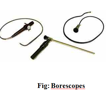
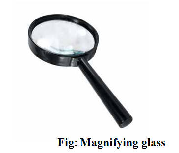
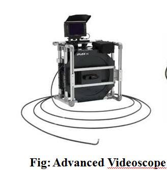
Visual testing is the most basic and common inspection method involves in using of human eyes to look for defects. But now it is done by the use special tools such as video scopes, magnifying glasses, mirrors, or borescopes to gain access and more closely inspect the subject area.
Visual Testing Equipments:
- Mirrors (especially small, angled mirrors),
- Magnifying glasses,
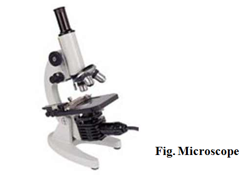
- Microscopes (optical and electron),
- Borescopes and fiber optic borescopes,
- Closed circuit television (CCTV) systems,
- Videoscope.
Visual Testing Equipments
Dye Penetrant Testing
This method is commonly used for detect the surface cracks or defects. Dye penetrant Testing (DPT) is one of the most widely used Non Destructive Testing (NDT) methods. DPT can be used to inspect almost any material provided that its surface is not extremely rough.
Dye Penetrant Testing Process
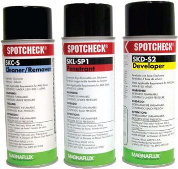
Three liquids are used in this method.
1.Cleaner
2.Penetrant
3.Developer
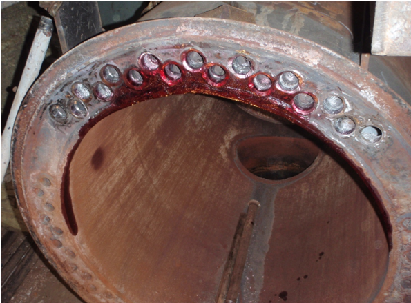
Dye Penetrant Testing of a Boiler
At first the surface of the material that is to be tested is cleaned by a liquid. The liquid is called cleaner.
Then a liquid with high surface wetting characteristics is applied to the surface of the part and allowed time to seep into surface breaking defects. This liquid is called penetrant. After five or ten minutes the excess penetrant is removed from the surface.
Then another liquid is applied to pull the trapped penetrant out the defect and spread it on the surface where it can be seen. This liquid is called deveoper.
Findings
After Dye Penetrant Testing there are two surface cracks are Detected.
Advantages of Dye Penetrant Testing
- This method has high sensitivity to small surface discontinuities.
- Large areas and large volumes of parts/materials can be inspected rapidly and at low cost.
- Indications are produced directly on the surface of the part and constitute a visual representation of the flaw.
- Aerosol spray can make penetrant materials very portable.
- Penetrant materials and associated equipments are relatively inexpensive.
Limitations of Dye Penetrant Testing
- Only surface breaking defects can be detected.
- Precleaning is critical since contaminants can mask defects.
- The inspector must have direct access to the surface being inspected.
- Surface finish and roughness can affect inspection sensitivity.
- Post cleaning of acceptable parts or materials is required.
- Chemical handling and proper disposal is required.
Magnetic Particle Testing
This method is suitable for the detection of surface and near surface discontinuities in magnetic material, mainly ferrite steel and iron. Magnetic particle Testing (MPT) is a nondestructive testing method used for defect detection. MPT is fast and relatively easy to apply, and material surface preparation is not as critical as it is for some other Non-Destructive Testing (NDT) methods.
Basic Principle of MPT
In the first figure the magnetized metal has no crack and there only two poles that is north pole and south pole. And in second figure the magnetized metal has a crack and at the crack point there creates another north and south pole for the magnetic flux leakage.
Magnetic Particle Testing Process
The first step in a magnetic particle testing is to magnetize the test component by a MPT equipment. If there any defects on the surface or near to the surface are present, the defects will create a leakage field.
Then finely milled iron particles coated with a dye pigment are applied to the specimen. These particles are attracted to magnetic flux leakage fields and will cluster to form an indication directly over the defects. This indication can be visually detected under proper lighting conditions.
Magnetic Particle Testing in Superheater Pipe Welding
First the welding joint is magnetized by MPT equipment. Then finely milled iron particles are applied to the magnetized weld joint.
Magnetic Particle Testing in Gas Pipe Welding:
Iron particles make a cluster at the welding joint for magnetic flux leakage because of welding defects.
Advantages Magnetic Particle Testing:
- It does not need very stringent pre-cleaning operation.
- It is the best method for the detection of surface and near to the surface cracks in ferromagnetic materials.
- Fast and relatively simple Non Destructive Testing (NDT) method.
- Generally inexpensive.
- Will work through thin coating.
- Highly portable NDT method.
- It is quicker.
Limitations of Magnetic Particle Testing:
- Material must be ferromagnetic.
- Orientation and strength of magnetic field is critical.
- Detects surface and near-to-surface discontinuities only.
- Large currents sometimes require.
Ultrasonic Testing
This technique is used for the detection of internal surface (particularly distant surface) defects in sound conducting materials. In this method high frequency sound waves are introduced into a material and they are reflected back from surface and flaws. Reflected sound energy is displayed versus time, and inspector can visualize a cross section of the specimen showing the depth of features.
Basic Principle of Ultrasonic Testing
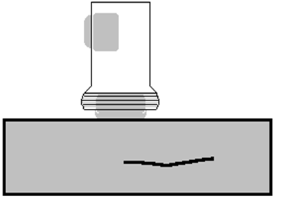
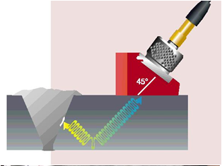
A typical UT system consists of several functional units, such as the pulser/receiver, piezoelectric transducer, and display devices. A pulser/receiver is an electronic device that can produce high voltage electrical pulses. Driven by the pulser, the transducer generates high frequency ultrasonic energy. The sound energy is introduced and propagates through the materials in the form of waves. When there is a discontinuity (such as a crack) in the wave path, part of the energy will be reflected back from the flaw surface. The reflected wave signal is transformed into an electrical signal by the piezoelectrical transducer and is displayed on a screen.
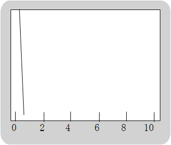
In the figure below, the reflected signal strength is displayed versus the time from signal generation, when a echo was received. Signal travel time can be directly related to the distance. From the signal, information about the reflector location, size, orientation and other features can sometimes be gained.