VISUAL INSPECTION
Introduction
VISUAL INSPECTION is a nondestructive testing technique that provides a means of detecting and examining a variety
of surface flaws, such as corrosion, contamination, surface finish, and surface discontinuities on joints (for example,
welds, seals, solder connections, and adhesive bonds). Visual inspection is also the most widely used method for detecting
and examining surface cracks, which are particularly important because of their relationship to structural failure
mechanisms. Even when other nondestructive techniques are used to detect surface cracks, visual inspection often
provides a useful supplement. For example, when the eddy current examination of process tubing is performed, visual
inspection is often performed to verify and more closely examine the surface disturbance.
Given the wide variety of surface flaws that may be detectable by visual examination, the use of visual inspection may
encompass different techniques, depending on the product and the type of surface flaw being monitored. This article
focuses on some equipment used to aid the process of visual inspection. The techniques and applicability of visual
inspection for some products are considered in the Selected References in this article and in the Section “Nondestructive
Inspection of Specific Products” in this Volume.
The methods of visual inspection involve a wide variety of equipment, ranging from examination with the naked eye to
the use of interference microscopes for measuring the depth of scratches in the finish of finely polished or lapped
surfaces. Some of the equipment used to aid visual inspection includes:
· Flexible or rigid borescopes for illuminating and observing internal, closed or otherwise inaccessible
areas
· Image sensors for remote sensing or for the development of permanent visual records in the form of
photographs, videotapes, or computer-enhanced images
· Magnifying systems for evaluating surface finish, surface shapes (profile and contour gaging), and
surface microstructures
· Dye and fluorescent penetrants and magnetic particles for enhancing the observation of surface cracks
(and sometimes near-surface conditions in the case of magnetic particle inspection)
This article will review the use of the equipment listed above in visual inspection, except for dye penetrants and magnetic
particles, which are discussed in the articles “Liquid Penetrant Inspection” and “Magnetic Particle Inspection,”
respectively, in this Volume.
Visual Inspection
Borescopes
A borescope (Fig. 1) is a long, tubular optical device that illuminates and allows the inspection of surfaces inside narrow
tubes or difficult-to-reach chambers. The tube, which can be rigid or flexible with a wide variety of lengths and diameters,
provides the necessary optical connection between the viewing end and an objective lens at the distant, or distal, tip of the
borescope. This optical connection can be achieved in one of three different ways:
· By using a rigid tube with a series of relay lenses
· By using a tube (normally flexible but also rigid) with a bundle of optical fibers
· By using a tube (normally flexible) with wiring that carries the image signal from a charge-coupled
device (CCD) imaging sensor at the distal tip
These three basic tube designs can have either fixed or adjustable focusing of the objective lens at the distal tip. The distal
tip also has prisms and mirrors that define the direction and field of view (see Fig. 2). These views vary according to the
type and application of borescope. The design of illumination system also varies with the type of borescope. Generally, a
fiber optic light guide and a lamp producing white light is used in the illumination system, although ultraviolet light can
be used to inspect surfaces treated with liquid fluorescent penetrants. Light-emitting diodes at the distal tip are sometimes
used for illumination in videoscopes with working lengths greater than 15 m (50 ft).
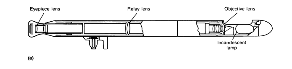
Rigid Borescopes
Rigid borescopes are generally limited to applications with a straight-line path between the observer and the area to be observed. The sizes range in lengths from 0.15 to 30 m (0.5 to 100 ft) and in diameters from 0.9 to 70 mm (0.035 to 2.75 in.). Magnification is usually 3 to 4×,
but powers up to 50× are available. The illumination system is either an incandescent lamp located at the distal tip end (Fig. 1a) or a light guide bundle made from optical fibers (Fig. 1c) that conduct light from an external source.The choice of viewing heads for rigid borescopes (Fig.
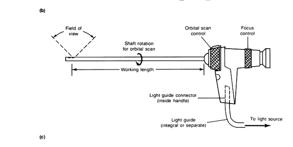
2) varies according to the application, as described in the section “Selection” in this article. Rigid borescopes generally have a 55° field of view, although the fields of view can range from 10 to 90°. Typically, the distal tips are not interchangeable, but some models (such as the
extendable borescopes) may have interchangeable viewing heads. Some rigid borescopes have orbital scan (Fig. 1c), which involves the rotation of the optical shaft for scanning purposes. Depending on the borescope model, the amount of rotation can vary from 120 to 370°. Some rigid borescopes also have movable prisms at the tip for scanning. Rigid borescopes are available in a variety of models having significant variations in the design of the shaft, the distal tip, and the illumination system. Some of these design variations are described below. Basic Design. The rigid borescope typically has a series of achromatic relay lenses in the optical tube. These lenses preserve the resolution of the image as it travels from the objective lens to the eyepiece. The tube diameter of these borescopes ranges from 4 to 70 mm (0.16 to 2.75 in.). The illumination system can be either a distal lamp or a light guide bundle, and the various features may include orbital scan, various viewing heads, and adjustable focusing of the objective lens. Miniborescopes. Instead of the conventional relay lenses, miniborescopes have a single image-relaying rod or quartz fiber in the optical tube. The lengths of miniborescopes are 110 and 170 mm (4.3 and 6.7 in.), and the diameters range from 0.9 to 2.7 mm (0.035 to 0.105 in.). High magnification (up to 30×) can be reached at minimal focal lengths, and an adjustable focus is not required, because the scope has an infinite depth of field. The larger sizes have forward, side view, and forward-oblique views. The 0.9 mm (0.035 in.) diam size has only a forward view. Miniborescopes have an integral light guide bundle. Hybrid borescopes utilize rod lenses combined with convex lenses to relay the image. The rod lenses have fewer glass-air boundaries; this reduces scattering and allows for a more compact optical guide. Consequently, a larger light guide bundle can be employed with an increase in illumination and an image with a higher degree of contrast. Hybrid borescopes have lengths up to 990 mm (39 in.), with diameters ranging from 5.5 to 12 mm (0.216 to 0.47 in.). All hybrid borescopes have adjustable focusing of the objective lens and a 370° rotation for orbital scan. The various viewing directions are forward, side, retrospective, and forward-oblique. Extendable borescopes allow the user to construct a longer borescopic tube by joining extension tubes. Extendable borescopes are available with either a fiber-optic light guide or an incandescent lamp at the distal end. Extendable borescopes with an integral lamp have a maximum length of about 30 m (100 ft). Scopes with a light guide bundle have a shorter maximum length (about 8 m, or 26 ft), but do allow smaller tube diameters (as small as 8 mm, or 0.3 in.). Interchangeable viewing heads are also available. Extendable borescopes do not have adjustable focusing of the objective lens.
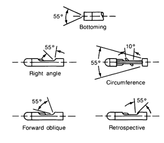
Fig. 2 Typical directions and field of view with rigid borescopes
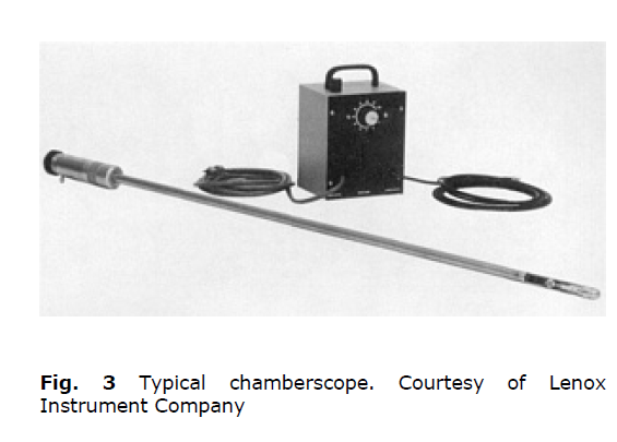
Rigid chamber scopes allow more rapid inspection of larger chambers. Chamber scopes (Fig. 3) have variable
magnification (zoom), a lamp at the distal tip, and a scanning mirror that allows the user to observe in different directions.
The higher illumination and greater magnification of chamber scopes allow the inspection of surfaces as much as 910 mm
(36 in.) away from the distal tip of the scope.
Mirror sheaths
Mirror sheaths can convert a direct-viewing borescope into a side-viewing scope. A mirror sheath is designed to fit over the tip of the scope and thus reflect an image from the side of the scope. However, not all applications are suitable for this device. A side, forward-oblique, or retrospective viewing head provides better resolution and a higher degree of image contrast. A mirror sheath also produces an inverse
image and may produce unwanted reflections from the shaft. Scanning. In addition to the orbital scan feature
described earlier, some rigid borescopes have the ability to scan longitudinally along the axis of the shaft. A movable prism with a control at the handle accomplishes this scanning. Typically, the prism can shift the direction of view through an arc of 120°.
Flexible Borescopes
Flexible borescopes are used primarily in applications that do not have a straight passageway to the point of observation.
The two types of flexible borescopes are flexible fiberscopes and videoscopes with a CCD image sensor at the distal tip.
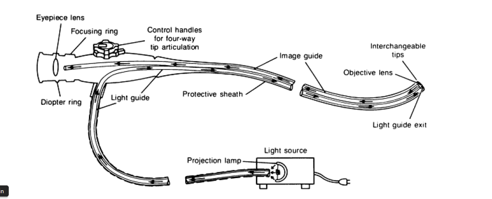
Flexible Fiberscopes. A typical fiberscope (Fig. 1b) consists of a light guide bundle, an image guide bundle, an
objective lens, interchangeable viewing heads, and remote controls for articulation of the distal tip. Fiberscopes are
available in diameters from 1.4 to 13 mm (0.055 to 0.5 in.) and in lengths up to 12 m (40 ft). Special quartz fiberscopes
are available in lengths up to 90 m (300 ft).
The fibers used in the light guide bundle are generally 30 m (0.001 in.) in diameter. The second optical bundle, called
the image guide, is used to carry the image formed by the objective lens back to the eyepiece. The fibers in the image
guide must be precisely aligned so that they are in an identical relative position to each other at their terminations for
proper image resolution.
The diameter of the fibers in the image guide is another factor in obtaining good image resolution. With smaller diameter
fibers, a brighter image with better resolution can be obtained by packing more fibers in the image guide. With higher
resolution, it is then possible to use an objective lens with a wider field of view and also to magnify the image at the
eyepiece. This allows better viewing of objects at the periphery of the image (Fig. 4). Image guide fibers range from 6.5
to 17 m (255 to 670 in.).
The interchangeable distal tips provide various directions and fields of view on a single fiberscope. However, because the
tip can be articulated for scanning purposes, distal tips with either a forward or side viewing direction are usually
sufficient. Fields of view are typically 40 to 60°, although they can range from 10 to 120°. Most fiberscopes provide
adjustable focusing of the objective lens.
Videoscopes with CCD probes involve the electronic transmission of color or black and white images to a video
monitor. The distal end of electronic videoscopes contains a CCD chip, which consists of thousands of light-sensitive
elements arrayed in a pattern of rows and columns. The objective lens focuses the image of an object on the surface of the
CCD chip, where the light is converted to electrons that are stored in each picture element, or pixel, of the CCD device.
The image of the object is thus stored in the form of electrons on the CCD device. At this point, a voltage proportional to
the number of electrons at each pixel is determined electronically for each pixel site. This voltage is then amplified,
filtered, and sent to the input of a video monitor.
Videoscopes with CCD probes produce images (Fig. 5) with spatial resolutions of the order of those described in Fig. 6.
Like rigid borescopes and flexible fiberscopes, the resolution of videoscopes depends on the object-to-lens distance and
the fields of view, because these two factors affect the amount of magnification (see the section “Magnification and Field
of View” in this article). Generally, videoscopes produce higher resolution than fiberscopes, although fiberscopes with
smaller diameter fibers (Fig. 4a) may be competitive with the resolution of videoscopes.
Another advantage of videoscopes is their longer working length. With a given amount of illumination at the distal tip,
videoscopes can return an image over a greater length than fiberscopes. Other features of videoscopes include:
· The display can help reduce eye fatigue (but does not allow the capability of direct viewing through an
eyepiece)
· There is no honeycomb pattern or irregular picture distortion as with some fiberscopes
· The electronic form of the image signal allows digital image enhancement and the potential for
integration with automatic inspection systems.
· The display allows the generation of reticles on the viewing screen for point-to-point measurements.
Special Features
Measuring borescopes and fiberscopes contain a movable cursor that allows measurements during viewing . When the object under measurement is in focus, the movable cursor provides a reference for dimensional measurements in the optical plane of the object. This capability eliminates the need to know the object-to-lens distance when determining magnification factors. Working channels are used in borescopes and fiberscopes to pass working devices to the distal tip. Working channels are presently used to pass measuring instruments, retrieval devices, and hooks for aiding the insertion of thin, flexible fiberscopes. Working channels are used in flexible fiberscopes with diameters as small as 2.7 mm (0.106 in.). Working channels are also under consideration for the application and removal of dye penetrants and for the passage of wires and sensors in eddy current measurements. Selection Flexible and rigid borescopes are available in a wide variety of standard and customized designs, and several factors can influence the selection of a scope for a particular application. These factors include focusing, illumination, magnification, working length, direction of view, and environment. Focusing and Resolution. If portions of long objects are at different planes, the scope must have sufficient focus adjustment to achieve an adequate depth of field. If the scope has a fixed focal length, the object will be in focus only at a specific lensto- object distance. To allow the observation of surface detail at a desired size, the optical system of a borescope must also provide adequate resolution and image contrast. If resolution is adequate but contrast is lacking, detail cannot be observed. In general, the optical quality of a rigid borescope improves as the size of the lens increases; consequently, a borescope
with the largest possible diameter should be used. For fiberscopes, the resolution is dependent on the accuracy of alignment and the diameter of the fibers in the image bundle. Smaller-diameter fibers provide more resolution and edge contrast (Fig. 4), when combined with good geometrical alignment of the fibers. Typical resolutions of videoscopes are given in Fig. 6. Illumination. The required intensity of the light source is determined by the reflectivity of the surface, the area of surface to be illuminated, and the transmission losses over the length of the scope. At working lengths greater than 6 m (20 ft), rigid borescopes with a lamp at the distal end provide the greatest amount of illumination over the widest area. However, the heat generated by the light source may deform rubber or plastic materials. Fiber-optic illumination in scopes
with working lengths less than 6 m (20 ft) is always brighter and is suitable for heat-sensitive applications because filters
can remove infrared frequencies. Because the amount of illumination depends on the diameter of the light guide bundle, it
is desirable to use the largest diameter possible. Magnification and field of view are interrelated; as magnification is increased, the field of view is reduced. The precise relationship between magnification and field of view is specified by the manufacturer. The degree of magnification in a particular application is determined by the field of view and the distance from the objective lens to the object. Specifically, the magnification increases when either the field of view or the lens-to-object distance decreases. Working Length. In addition to the obvious need for a scope of sufficient length, the working length can sometimes dictate the use of a particular type of scope. For example, a rigid borescope with a long working length may be limited by the need for additional supports. In general, videoscopes allow a longer working length than fiberscopes.
Direction of View. The selection of a viewing direction is influenced by the location of the access port in relation to the object to be observed. The following sections describe some criteria for choosing the direction of view shown in Fig. 2. Flexible fiberscopes or videoscopes, because of their articulating tip, are often adequate with either a side or forward viewing tip. Circumferential or panoramic heads are designed for the inspection of tubing or other cylindrical structures. A centrally located mirror permits right-angle viewing of an area just scanned by the panoramic view. The forward viewing head permits the inspection of the area directly ahead of the viewing head. It is commonly used
when examining facing walls or the bottoms of blind holes and cavities.
Courtesy of Olympus Corporation Forward-oblique heads bend the viewing direction at an angle to the borescope axis, permitting the inspection of corners at the end of a bored hole. The retrospective viewing head bends the cone of view at a retrospective angle to the
borescope axis, providing a view of the area just passed by the advancing borescope. It is especially suited to inspecting
the inside neck of cylinders and bottles. Environment. Flexible and rigid borescopes can be manufactured to withstand a variety of environments. Although most scopes can operate at temperatures from -34 to 66 °C (-30 to 150 °F), especially designed scopes can be used at
temperatures to 1925 °C (3500 °F). Scopes can also be manufactured for use in liquid media. Special scopes are required for use in pressures above ambient and in atmospheres exposed to radiation. Radiation can cause the multicomponent lenses and image bundles to turn brown. When a scope is used in atmospheres exposed to radiation, quartz fiberscopes are generally used. Scopes used in a gaseous environment should be made explosionproof to minimize the potential of an accidental explosion.
Applications
Rigid and flexible borescopes are available in different designs suitable for a variety of applications. For example, when inspecting straight process piping for leaks rigid borescopes with a 360° radial view are capable of examining inside diameters of 3 to 600 mm (0.118 to 24 in.). Scopes are also used by building inspectors and contractors to see insidewalls, ducts, large tanks, or other dark areas. The principal use of borescope is in equipment maintenance programs, in which borescopes can reduce or eliminate the need for costly teardowns. Some types of equipment, such as turbines, have access ports that are specifically designed for borescopes. Borescopes provide a means of checking in-service defects in a variety of equipment, such as turbines.Borescopes are also extensively used in a variety of manufacturing industries to ensure the product quality of difficult-toreach components. Manufacturers of hydraulic cylinders, for example, use borescopes to examine the interiors of bores for pitting, scoring, and tool marks. Aircraft and aerospace manufacturers also use borescopes to verify the proper placement and fit of seals, bonds, gaskets, and subassemblies in difficult-to-reach regions.
NOTE: Continue our next visual inspection discussion on tomorrow…