API 510 Question

API 510 Question

1.A PQR was qualified in SG position using a new welder. But production welding is to be done by   the same welder in 3G position. Which of the following are applicable as a minimum?

  1. Both procedure and welder shall be re-qualified in 2G position.
  2. The qualified procedure can be used, only welder needs to be re-qualified in 3G position.
  3. The welder is qualified, but the procedure needs re­-qualification.
  4. Both procedure and welder need not be re-qualified.

2.A procedure is required with preheat temp = 2S0oF. Two WPS were made based on this PQR. All other parameters being same WPS (A) showed preheat temp = 280°F and WPS (B) showed preheat temp = 140°F, will you:

  1. Reject (A) & (B)
  2. Accept (A) only
  3. Accept (B) only
  4. Accept both

3.In a certain PQR for SMAW, the electrodes used for all passes were of AWS classification (E7018). Corresponding WPS also showed filler materials as E 7018. Now the manufacturer proposes to change the filler material in WPS to E 701S. Will you ask manufacturer to:

  1. Quality new PQR with E 7015 electrodes.
  2. Revise only WPS showing the change from E 7018 to E7015 and submit WPS as a new    revision.
  3. Revise only the PQR showing the change and resubmit for approval.
  4. Revise both WPS and PQR showing the change and resubmit for approval.

4.A PQR in GTAW process was qualified with PWHT with A 516 grade 70 materials, ¾” thick. The thickness for production welds is 1.0”, but without PWHT. The manufacturer claims that same PQR will be O.K. What is your assessment?

  1. It qualifies required conditions hence no new PQR is required.
  2. It qualifies thickness but not It does not qualify “No PWHT” condition, hence new PQR is   required.
  3. It qualifies “no PWHT” condition, but not thickness. New PQR is required.
  4. It does not qualify both thickness as well as “No PWHT” – condition, hence new PQR is    required. ­

5.For 515 grade 60 material, the following results were obtained for two tensile test specimen during   a PQR qualification.

Specimen T1: failed in B.M. at 57,400 psi

Specimen T2: failed in weld metal, at 59,500 psi

Your assessment is:

  1. PQR test is OK since both are within acceptance criteria
  2. PQR test is rejected as both T1 and T2 are not within the acceptance criteria
  3. PQR in rejected because T1 is OK but T2 has failed
  4. PQR in rejected because T1 is failed thoughT2 is OK

6.A procedure is qualified with Base metal THK. = 20mm. Two WPS were made based on this PQR. Other parameters being same, WPS (A) showed Base Metal Thk. = 38 mm and WPS (B) showed Base Metal Thk. = 6mm.

Your assessment is:

  1. Reject (A) & (B)
  2. Accept (A) only
  3. Accept (B) only
  4. Accept both

7.A welder has made 25 SMAW groove welds, but the guided bend test for the welder’s qualification was never performed. In order to avoid cutting out all of the production welds made by this welder, which of the following minimum steps would be taken to validate the qualification?

  1. Radiograph the welder’s first production weld and accept the qualification based on acceptable weld quality by radiography.
  2. There is no alternative to qualifying a welder by the guided bend test.
  3. Have the welder prepare a test coupon and have the bend test done on that. If bend test is okay,    accept the welds already made.
  4. Radiograph all 25 welds, regardless of the governing specifications for sample selection.

8.In a radiographic examination of butt weld (Thk= 3.5 in.) the Geometric un-sharpness shall not exceed?

  1. 0.02″
  2. 0.04″
  3. 0.03″
  4. None of above

9.Select suitable Hole Type (Source Side) penetrameter for following weld joint:

Base Mertal Thk. = 7/8”

Backing Strip Thk. = 3/16”

Weld Re-enforcement Thk. = 1/8”

  1. No. 20
  2. No. 25
  3. No. 30
  4. None of the above

10.If type of penetrameter in above question is changed to wire type what shall be the wire designation (wire diameter In Inch)?

  1. 0.025 dia. (No.10)
  2. 0.016 dia. (No. 8)
  3. 0.032 dia. (No.11)
  4. None of the above

11.For steel plates and welds to be checked by LPI what shall be the penetration time for the Penetrant?

  1. 10 min for weld, 5 min for plate
  2. 5 min for both
  3. 10 min for both
  4. 5 min for weld, 10 min for plate

12.After applying the developer the examiner checked four welds for surface defects after following period, weld A after 5 minute, weld B after 10 minutes, weld C was checked after 30 minutes and welds D after 65 minutes. Which of the welds were checked wrongly?

  1. Weld A and B
  2. Weld C and D
  3. Weld D only
  4. Weld A and D

13.For MT examination by Prod Technique the spacing between prods shall be between?

  1. 4 inch to 12 inch
  2. 4 inch to 10 inch
  3. 3 inch to 10 inch
  4. 3 inch to 8 inch

14.Calculate estimated inspection period for external and internal inspection for a vessel whose remaining life is estimated as 12 years?

  1. Internal = 6 years, external = 10 years
  2. Internal = 6 years, external = 5 years
  3. Internal = 5 years, external = 10 years
  4. None of the above

15.As per WPS the material used is SAS16 Gr.70 and the electrode used is E-7018. What are the P. No. and F No.?

  1. 1 and 4
  2. 4 and 1
  3. 2 and 4
  4. 4 and 2


­Q. NO. ANSWER
1 D
2 B
3 B
4 B
5 C
6 D
7 A
8 B
9 B
10 D
11 D
12 D
13 D
14 B
15 A


Welding Joints- Diffternt Types


Welding Joints

Diffternt types of  Welding Joints

Five Basic Welding Joints:

1. Butt Joint

2. Corner Joint

3. T – Joint

4. Lap Joint

5. Edge Joint

Butt Joint:

Butt joint- a joint between two members aligned approximately in the same plane

Different Edge Shapes and Symbols for some Butt-Joints:

Welding Joints

Corner Joint:

Corner joint – a joint between two members located at right angles to each other

Some Different Edge Shapes and Symbols for Corner Joints:

Welding Joints

T-Joint:

T- joint – a joint between two members located approximately at right angles to each other in the form of a T

Some Different Edge Shapes and Symbols for T-Joint:

Welding Joints

Lap Joint:

Lap Joint- a joint between two overlapping members

Some Different Edge Shapes and Symbols for Lap Joints:

Welding Joints

Edge Joint:

Edge joint- a joint between the edges of two or more parallel or nearly parallel members

Some Different Edge Shapes and Symbols for Edge Joints:

Welding JointsWelding Joints Welding Joints Welding Joints Welding Joints Welding Joints Welding Joints Welding Joints Welding Joints Welding Joints Welding Joints Welding Joints Welding Joints


WELDING PROCESS | ESL SCHOOL OF WELDING | TIG-MIG-ARC TRAINING

WELDING PROCESS

RESPONSIBILITIES OF A WELDING ENGINEER

BEFORE WELDING:

  • REVIEWING OF DRAWINGS AND     SPECIFICATIONS
  • CHECKING OF QUALIFICATION OF PROCEDURES TO BE USED
  • REVIEWING OF MATERIALS TO BE USED (WELDING CONSUMABLE, SHIELDING GAS, BACKING, etc)
  • CHECKING OF SURFACE CLEANLINESS
  • CHECKING FITUP AND ALIGNMENT OF WELD JOINTS

DURING WELDING:

  • PREHEAT TEMPERATURE
  • QUALITY OF ROOT BEAD
  • INTERPASS TEMP.
  • SEQUENCE OF WELD PASS
  • INTER PASS CLEANING
  • CONFORMANCE TO APPLICABLE PROCEDURE (VOLTAGE, CURRENT, HEAT INPUT AND TRAVEL SPEED)

AFTER WELDING:

  • POST HEATING
  • FINAL WELD APPEARANCE
  • PRESENCE OF DISCONTINUITIES
  • POST WELD HEAT TREATMENT
  • AMOUNT OF DISTORTION

WELDING:

  • Welding joins two pieces of metal / material by the use of heat, pressure, or both
  • Brazing or soldering involves a filler metal which has a lower melting point than the metal pieces to be joined
  • Metal cutting is done by heating the metal with a flame and directing a stream of pure oxygen along the line to be cut

WELDING PROCESSWELDING PROCESSES:

COMMON WELDING PROCESSES:

1.SHIELDED METAL ARC WELDING

2.SUBMERGED ARC WELDING

3.GAS TUNGSTEN ARC WELDING

4.FLUX CORED ARC WELDING

CODES, STANDARDS AND SPECIFICATIONS TO BE FOLLOWED FOR FABRICATION:

  • ASME
  1. SEC. IX FOR WELDING PROCEDURE SPECIFICATION
  2. SEC. IIC FOR WELDING CONSUMABLE SELECTION
  3. SEC.IIA FOR FERROUS METAL SPECIFICATION
  4. SEC.VIII FOR PRESSURE VESSEL FABRICATION
  • EN 288 FOR WPS QUALIFICATION & EN 287 FOR WPQ.
  • IBR

MANUFACTURING PRODUCTS:

I) HEADERS:                                         V) COILS:

WATER WALL HEADER            1. ECONOMISER COIL

SUPER HEATER HEADER            2. SUPER HEATER COIL

REHEATER HEADER            3. EVAPOURATOR COIL

ECONOMISER HEADERS            4. BED SUPER HEATER

DRAIN HEADERS

II) DRUM:

HP DRUM

LP DRUM

STEAM DRUM

III) STORAGE TANK

IV) DEAERATOR

WPS & PQR:

Welding Procedure Specification:

It is a written document that provides direction to the welder for making production welds in accordance with code requirements.

Any WPS must be qualified by the manufacturer.

WPS specifies the condition (ranges) under which welding must be performed called variables.

WPS addresses essential, supplementary essential and non essential variables

Purpose of WPS Qualification:

To determine that the weldment is capable of providing the required properties for the intended application.

WPS establishes the properties of the weldment and not the skill of the welder.

Procedure Qualification Record:

It documents what occurred during welding the test coupon and the results of the test coupon.

PQR documents the essential variables and other specific information and the results of the required testing. In addition, when notch toughness is required for procedure qualification, the applicable supplementary essential variables shall be recorded.

Procedure Qualification:

PQR is a record of welding data to weld a test coupon. It also contains test results.

Completed PQR shall document all essential variables including ranges.

PQR to be certified accurate and shall not be subcontracted.

If more than one process then weld deposit thickness for each process and filler metal to be recorded.

Weld Orientation:

Plate groove positions 1G, 2G, 3G, 4G

Pipe groove positions 1G, 2G, 5G, 6G

Plate fillet positions 1F, 2F, 3F, 4F

Pipe fillet positions 1F, 2F, 2FR, 4F, 5F

1F – 0 to 30

2F – +15 -10 wrt 45

4F – 0 – 125

3F – 125 – 235

Base Metal Classification:

P nos depend on composition, weldability & mechanical properties.

Group nos classify metals within P nos for procedure qualification where notch toughness requirements are specified. But base metals can not be indiscriminately substituted.


ULTRASONIC TESTING | ESL INDUSTRIAL SUPPORT SERVICES | QUESTION BANK

ULTRASONIC TESTING

QUESTION BANK

ultrasonic testing

ULTRASONIC TESTING:

  • Ultrasonic testing uses high frequency sound energy to conduct examinations and make measurements.
  • Ultrasonic examinations can be conducted on a wide variety of material forms including castings, forgings, welds, and composites.
  • A considerable amount of information about the part being examined can be collected, such as the presence of discontinuities, part or coating thickness; and acoustical properties can often be correlated to certain properties of the material.

1.The displacement of particles from its mean position is called

  1. Mean free path
  2. Cycle
  3. Wave length
  4. Vibration

2.Ultrasonic waves pass through

  1. Solids
  2. Liquids
  3. Gases
  4. a, b & c
  5. Solids, liquids, gases except vacuum.

3.If wave length is increased, the frequency will

  1. Increase
  2. decrease
  3. Remains the same
  4. None of the above
  5. All the above.

4.Calculate the frequency for a wave length of 1.5 mm at a velocity of 6.1 km/sec.

  1. 3 MHZ
  2. 4 MHZ
  3. 5 MHZ
  4. 4 MHZ

5.Longitudinal waves are the ones in which the particle motion is

  1. Perpendicular to the direction of propagation
  2. In the same direction of propagation
  3. Elliptical in the direction of prorogation
  4. Is dispersive.

6.The wave which travels through solids, liquids and gases is

  1. Longitudinal wave
  2. Surface wave
  3. Shear wave
  4. Plate waves

7.The transverse waves do not propagate through liquids and gases because

  1. Liquids and gases don’t posses modules of elasticity
  2. The alteration between actions or modules is small
  3. Either (a) or (b)
  4. None of the above

8.Lamb waves are used to inspect

  1. Bar stock
  2. forging
  3. Thick plates
  4. Thin sheets


9.The general law that explains wave behavior at the interface is called

  1. Einstein’s theory
  2. Huygens’s principle
  3. Newton’s Law
  4. Snell’s Law


10.Second critical angle is the angle of incidence at the interface of the dissimilar materials when

  1. Mode converted longitudinal wave angle becomes 90°
  2. Refracted, mode converted transverse wave angle becomes 90° resulting of which surface wave is generated at the plane of boundary
  3. Mode converted longitudinal wave is eliminated from the second medium
  4. (b) or (c)


11.Surface wave is generated at the boundary of Perspex and steel, at

  1. First critical angle
  2. The incidence angle of 40°
  3. Second critical angle
  4. Both a & b


12.Bending of sound waves at the tip or edge of a discontinuity is

  1. reflection
  2. refraction
  3. Interference
  4. diffraction
  5. c & d


13.The zone where the defect size can not be estimated exactly due to interference of wave fronts is

  1. Far field
  2. Fresnel zone
  3. Near Field
  4. (b) or (c)


14.The sound intensity in far zone decrease with the

  1. Distance of its travel
  2. length of refracted wave length
  3. Distance of travel and also across the beam
  4. both (b) and (c)


15.When frequency and dia of a crystal is decreased, the beam spread would be

  1. decreased
  2. increased
  3. No change
  4. either (a) or (b)


16.Beam divergence is a function of the diameter of the crystal and the wave length of the beam transmitted through a medium and it

  1. Increases if the frequency or crystal diameter is increased
  2. Decreases if the frequency or crystal diameter is decreased
  3. Increases if the frequency is increased and crystal diameter is decreased
  4. Decreases if the frequency is decreased and the crystal diameter is decreased
  5. None


17.A search unit that contains three or more individual transducer elements is known as

  1. Dual transducer
  2. Probe
  3. Mosaic transducer
  4. None of the above


18.Scattering of an ultrasonic wave occurs due to

  1. Homogeneous condition
  2. Non – homogeneous condition of materials like grain boundaries and minute non – metallic inclusions
  3. Diffraction
  4. Refraction


19.A-Scan equipment displays a data presentation which is related to

  1. Plan view of the area under inspection.
  2. Cross sectional view
  3. Elapsed time & elapsed time, from left to right and signal amplitude


20.The control which is taking care of frequency amplitude and the pulse repetition rate is

  1. Pulse length
  2. Amplifier
  3. Pulsar
  4. Receiver

21.Both the delay and range controls are

  1. In pulsar unit
  2. Rejection control
  3. Part of sweep generator
  4. None


22.In ultrasonic testing, the time duration of the transmitted pulse is referred to as

  1. the pulse amplitude
  2. pulse length or width
  3. the pulse shape
  4. None of the above.

23.An ultrasonic testing instrument that displays pulses representing the magnitude of reflected ultrasound as a function of time or depth of metal is said to contain

  1. continuous display
  2. `A’ scan presentation
  3. `B’ scan presentation
  4. `C’ scan presentation


24.The pulse repetition rate for thicker materials and thinner materials?

  1. Same
  2. lower
  3. higher
  4. higher for thinner and lower for thicker material

25.The echoes should always be read from

  1. Trailing part touching base line
  2. Height of the peak
  3. Foot of the leading echo

26.The crystal which can be used at elevated temperature is

  1. Lithium sulphate
  2. Polarized ceramics
  3. Quartz x-cut
  4. Both a & b

27.The Curie point or critical temperature is defined as

  1. The temperature at which the vibration of crystal suddenly falls to 50%.
  2. The temperature at which the vibration of crystal suddenly falls to 0%
  3. The temperature at which the crystal loses its piezo electric properties
  4. a & b

28.The efficiency of a transducer is described as

  1. Sensitivity
  2. Resolution, efficiency
  3. Sensitivity, resolution & energy conversion
  4. a & b & c

29.When using two separate search units, one a transmitter and another as receiver, the most efficiency combination is

  1. Quartz transmitter Lithium Sulphate as receiver
  2. Lithium Sulphate transmitter, Quartz as receiver
  3. Barium Titanate as transmitter and Lithium Sulphate as receiver
  4. Lithium Sulphate as transmitter and Barium Titanate as receiver.

30.The testing technique in which the crystal or transducer is parallel to the test surface and ultrasonic waves enter the material being tested in a direction perpendicular to the test surface is

  1. Angle beam
  2. Normal beam
  3. straight beam
  4. b or c
  5. surface beam

31.The advantages of using dual probe is

  1. Dead zone is eliminated
  2. The best of transmitters and receivers could be used as option
  3. We can use any range of frequency
  4. both a & b

32.By using immersion testing,

  1. Gross defects are noted
  2. Sensitivity is reduced
  3. Near surface resolution is achieved
  4. None of the above

33.The reason for attaching lenses to the transducer in immersion testing is

  1. to enhance sensitivity
  2. to reduce resolution
  3. to enhance resolution
  4. both a & c,
  5. both a & b

34.Line of focus is achieved in

  1. Spherical lens
  2. cylindrical lens
  3. Round lens
  4. point lens

35.With the aid of cylindrical lens, we will be able to achieve

  1. Line focus
  2. Point focus
  3. both a & b
  4. None


36.By using delay tip units, we are able to eliminate.

  1. Resolving power
  2. Sensitivity
  3. both a & b
  4. Dead zone

37.When using focused transducers non-symmetry in a propagation sound beam may be caused by

  1. Backing materials vibrations
  2. Porosity in lenses
  3. Lens centering or misalignment
  4. All of the above.

38.Which of the following test system has the best near resolution of the same frequencies?

  1. Straight beam probe with rubber membrane
  2. Straight beam probe with perspex delay
  3. Straight beam probe without protecting membrane
  4. Straight beam probe with low pulse strength

39.The efficiency to resolve two discontinues at different depths would be improved by

  1. Decreasing the frequency
  2. Shortening the pulse duration
  3. Increasing the amplitude
  4. None

40.The resolving power for frequency 4 MHZ compared to 2 MHZ is

  1. Same
  2. Worse
  3. Better
  4. None
Q.No Answer Q.No Answer
1 4 21 3
2 5 22 2
3 2 23 2
4 2 24 4
5 2 25 1
6 1 26 3
7 3 27 3
8 4 28 3
9 2 29 3
10 2 30 4
11 3 31 4
12 4 32 3
13 4 33 4
14 3 34 2
15 2 35 1
16 5 36 4
17 4 37 4
18 2 38 1
19 3 39 2
20 3 40 3

EDDY CURRENT TESTING | NDT TRAINING | ESL INDUSTRIAL SUPPORT SERVICES

EDDY CURRENT TESTING

QUESTION BANK

1.In a feed through encircling coil eddy current system, what would be the purpose of running a calibration defect several times but in various positions (such as top, bottom, left and right)?

  1. To check the phase selectivity
  2. To ensure proper centring of the material in the test coil
  3. To select the modulation analysis setting
  4. To select the proper operation speed

2.In a feed through encircling coil eddy current system, a calibration standard may be used to:

  1. Insure repeatability of the setup
  2. Calibrate the approximate depth of the detectable flaws
  3. Both a and b
  4. Measure the test frequency

3.A calibration standard may be used with a spinning probe eddy current instrument to:

  1. Produce an indication relative to the depth of the flaw
  2. Check the instrument for reliability and freedom from drift
  3. Check probe coil for possible damage
  4. All of the above

4.Spinning probe type eddy-type eddy current instruments are most useful in:

  1. Detection of surface and subsurface inclusions
  2. Detection of surface defects such as overlaps and seams
  3. Detection of internal piping or burst
  4. All of the above

5.A product can be viewed in terms of electrical magnetic effects. A diameter change of the product in an encircling coil is:

  1. An electrical effect
  2. A conductivity effect
  3. A magnetic effect
  4. All of the above

6.In figure 9, AC flowing through a primary coil set-up a magnetic field and causes a flow of eddy currents in the rod. The voltage of the secondary coil is dependent upon:

et1

  1. These eddy currents
  2. The primary coil
  3. The generator
  4. All of the above

7.Which of the following is not a method that may be used to improve the signal-to-noise ratio?

  1. Change to test frequency that will decrease the noise
  2. Increase the amplification of the test instrument
  3. Improve the fill factor
  4. Add filter circuits to the instruments

8.In eddy current testing, the theoretical maximum testing speed is determined by the:

  1. Magnetic flux density
  2. Testing frequency
  3. Conveyor drive
  4. Test coil impedance

9.In eddy current testing of ferromagnetic materials, the dc saturating field may be provided by :

  1. An encircling solenoid
  2. A magnetic yoke
  3. Both a and b
  4. None of the above

10.Which of the following is a property of eddy currents induced in a conductor by an encircling coil?

  1. The magnitude of eddy current flow is large compared to the current flow in the coil
  2. The eddy current flow is affected by permeability variation in the samples
  3. The eddy current flow dissipates no power in the conductor
  4. None of the above

11.Which of the following is a property of eddy currents induced in a homogeneous conductor by an encircling coil?

  1. They are weakest on the conductor surface
  2. The phase of the eddy currents varies through out the conductor
  3. They travel in straight lines
  4. They are maximum along the coil axis.

12.Which factor does not affect the phase shift between the transmitted signal and the reflected signal for a reflection type coil(assuming the part is nonferromagnetic)?

  1. The conductivity of the sample
  2. The magnitude of the transmitted signal
  3. The signal of the sample
  4. The presence of defects in the sample

13.Lift-off certainly reduces the amplitude of the flux leakage signal. The other significant effect it has on the signal is a change in:

  1. Phase
  2. Frequency
  3. Increasing lift-off which reduces the apparent width of the defect
  4. None of the above

14.The tubular product parameter having the greatest influence on the flux density of the magnetic field in the part (assuming the magnetizing force, H, remains constant)is the :

  1. Surface roughness of the product
  2. Diameter of the product
  3. Wall thickness of the product
  4. Length of the product

15.Any handling of equipment used in an eddy current system must take into consideration:

  1. The operator ‘s abilities
  2. The use of the product being tested
  3. Speed, frequency of test, sorting speed, and physical control of the product
  4. All of the above

16.An eddy current system lends itself to quality ratings such as “Quality Number” where the product being inspected:

  1. Is not defective
  2. Does not allow defective areas to be removed
  3. Is of inferior quality
  4. Has inconsistent quality

17.When inspecting material with eddy currents in an automatic handling system, it is advisable to calibrate and adjust the sensitivity levels to:

  1. Some electroic source
  2. Another NDT method
  3. An NBS standard
  4. An actual testpart being inspected

18.A distinct advantage of using handling equipment in an eddy current test system is to reduce the error caused by:

  1. Instrument drift
  2. Lift-off
  3. Skin effect
  4. All of the above
  5. None of the above

19.Decreased coupling or fill factor results in decreased test sensitivity because:

  1. Reduced coupling between the driver coil and the specimen induces less eddy current flow in the specimen
  2. Reduced coupling between the specimen and the pickup coil results in smaller voltages across the pickup coil
  3. Electrical circuits designed to provide fill factor compensation may prove to be inadequate, depending upon the extent of fill factor loss
  4. All of the above

20.Why is it desirable to hold the factor or lift-off constant?

  1. To avoid arcing between the coil and the specimen
  2. To minimize tester output signal changes that are not relevant to conditions with in the specimen to be tested.
  3. A fill factor or lift-off change will shift the operating frequency
  4. To minimize the load on the constant current ac excitation circuits

21.The reactance component is decreased by placing a conducting object in the coil’s electromagnetic field. Why is this so?

  1. The secondary field is exactly in phase with the primary field
  2. The secondary field is at precisely 90 degrees with the primary field
  3. The phase angle between the two field components is always greater than 90 degrees which partially cances the primary field
  4. The secondary field is 180 degrees out of phase with the primary field which causes a large phase shift

22Test coils may be shielded with conducting material or magnetic material to:

  1. Shape field
  2. Increase sensitivity
  3. Increase resolution
  4. All of the above
  5. None of the above

23.When a magnetic bar is placed in the coil’s electromagnetic field,the coil’s reactance is increased. What causes this phenomena?

  1. The coil becomes magnetic ally saturated
  2. The permeability raises the inductance of the test coil
  3. The magnetic test sample’s conductivity increases the reactance value of the coil
  4. This effect is described mathematically by thr equation B/H=μ

24.When an excitation voltage is applied to a primary winding, only the magnetic flux is in phase and the secondary magnetic flux is minor. When a test object is inserted in this coil, what action takes place?

  1. The object gets hot and no information is available
  2. Insertion of the object cancels all information
  3. The insertion of the test object intensifies the secondary magnetic flux producing a new total magnetic flux which can be used to supply test information
  4. By subtracting the primary voltage from the secondary voltage, the net voltage is obtained

25.The test coil excitation current should be held constant so that the test piece information obtained by an eddy current system will:

  1. Contain only flaw information and not indicate variations in magnetic field strength
  2. Not contain signals generated by cross talk
  3. Not contain electrical noise
  4. All of the above

26.Eddy currents flowing in the test object at any depth produce magnetic fields at greater depths, which oppose the primary field, thus breducing its effect and causing what kind of change in current flow as depth increases?

  1. A decrease
  2. An increase
  3. A frequency change
  4. None of the above

27.Skin effect causes eddy currents to tend to flow near the surface of the test piece. Which of the following factors alter the skin effect?

  1. Testing frequency
  2. Test piece temperature
  3. Test piece hardness
  4. Test piece permeability
  5. None of the above

28.Which of the following is not a common undesirable effect to the test caused by the testing environment?

  1. Temperature variation
  2. Crack in test sample
  3. Test object making contact with test coil
  4. Foreign object in the test coil field
  5. Test coil vibration

39.There is one function that responds to variations in eddy current flaw and magnetic field conditions. This function actually produces the output signal from the coil. What is this function?

  1. Phasing
  2. Resistance
  3. Reactance
  4. Impedance

30.The inductive reactance of a test coil, which is one of the most importance impedance quantities, depends upon which of the following?

  1. Frequency, coil inductance, coil resistance
  2. Coil inductance only
  3. Coil resistance and coil inductance only
  4. Frequency and coil resistance only
  5. Frequency and coil inductance only

31.An ac current produces eddy currents in a test object. The vector Hp represents the secondary ac field in the test piece. What function occurs to produce a workable test situation? (See figure 10)et2

  1. Changes in the test specimen such as a crack, metallurgical and dimensional change alter the secondary field phase and amplitude
  2. The primary ac current must be 60 cycles to produce this effect
  3. A temperature raise in the specimen
  4. A mismatch of the Hp and Hs fields produces a change in the output

32.To separate cracks and diameter effects for steel cylinders, the optimum frequencies correspond to f/fg ratios of less than (see figure 11)

et3

  1. 10
  2. 15
  3. 50
  4. 100
  5. 150

33.Thin –walled tubes should be tested for cracks, alloy or wall thickness at frequency ratios between(see Figure 12):

et4

  1. 0.1 and 0.4
  2. 0.4 and 2.4
  3. 2.4 and 4.0
  4. 4.0 and 10

34.Figure 13 indicates that the largest eddy current indicates from subsurface cracks will occur when the frequency ratio(f/fg) is:

et5

  1. 5 or less
  2. 15
  3. 50
  4. 150 or more


35.Figure 13 indicates that the magnitude of a signal from a surface crack will increase when the frequency ratio(f/fg):

  1. Remains the same
  2. Decreases
  3. Increases
  4. None of the above

36.Figure 14 indicates that when inspecting for surface cracks in nonferromagnetic cylinders, the optimum frequency ratio (f/fg) is between :

et6

  1. 5 and 10
  2. 10 and 50
  3. 50 and 100
  4. 100 and 150

37.An operating frequency of 100 khz will have the deepest penetration in:

  1. Titanium
  2. Copper
  3. Stainless steel
  4. Aluminum

38.As the operating frequency is increased, the impedance of the empty coil:

  1. Increases
  2. Decreases
  3. Remains the same
  4. None of the above

39.Disadvantage of using a surface probe coil for the inspection of small diameter tubing include:

  1. Inability to detect small discontinuities
  2. Slow inspection speed
  3. Inherent mechanical problem
  4. Both a and c
  5. Both b and c

40.Differntial coil system can be of which of the following types? (See figure 15)

et7

  1. Sketch no. 1
  2. Sketch no. 2
  3. Sketch no. 3
  4. All of the above
  5. Both a and b

EDDY CURRENT QB 1

ANSWERS

Q.NO ANSWERS Q.NO ANSWERS
1 2 21 3
2 1 22 4
3 4 23 2
4 1 24 3
5 3 25 1
6 4 26 1
7 2 27 5
8 2 28 2
9 3 29 4
10 2 30 5
11 2 31 1
12 2 32 1
13 2 33 2
14 3 34 1
15 4 35 2
16 2 36 2
17 4 37 3
18 2 38 1
19 4 39 5
20 2 40 4


Visual Testing | VT | Non Deatructive testing | VT Training in Trichy


VISUAL TESTING


Visual Testing:

Introduction:

Based on the principle of illuminating the object by light in the visible region of the electro magnetic wave spectrum.

One of the first, natural, methods of testing of anything we use is visual testing.visual testingPrerequisites:

  • Eye – The sensor;
  • Light – The probing medium.

Requirements:

  • Testing of the vision of the inspector, measurement with a light meter of the light falling on the specimen and establishing the actual ability to see the area being inspected.
  • Refer the code for the specifications.

Eye:

visual testing

Calibration of Eye:

  • Near Vision Acuity;
  • Colour blindness.

Near Vision Acuity Chart:

visual testingIshihara Chart:

visual testingLighting:

visual testingSteps:

  • Clean the test object sufficient enough to observe the details.
  • Keep it in a well illuminated space – generally 800 – 1000 lux.
  • Inspect the object by eye or by light sensitive devices such as photocells.

Aids for visual testing:

  • Mechanical aids;
  • Optical aids.

Mechanical Aids:

  • Measuring rules & tapes;
  • Calipers & micrometers;
  • Squares and angle measuring devices;
  • Thread, pitch and thickness gages;
  • Level gages (liquid & laser) and plumb lines;
  • A variety of weld gages.

Scale:visual testing

Parallax Error:

visual testing

Correct Usage:

visual testing

PI Tape:

visual testing

Vernier Scale:

visual testingMicrometer:

visual testingWeld Gauge:

visual testingOptical aids for visual testing:

  • Mirrors (especially small, angled mirrors);
  • Magnifying glasses, eye loupes, multilens magnifiers, measuring magnifiers;
  • Microscopes (optical and electron);
  • Optical flats (for surface flatness measurement);
  • Borescopes and fiber optic borescopes;
  • Optical comparators;
  • Photographic records;

Microscope:

visual testingMagnifying Lens:

visual testingOptical aids for visual testing:

  • Closed circuit television (CCTV) systems (alone and coupled to borescopes/microscopes);
  • Machine vision systems;
  • Positioning and transport systems (often used with CCTV systems);
  • Image enhancement (computer analysis and enhancement).

Enhancement Techniques in  visual testing:

  • 1. Microscope.
  • 2. Borescope.
  • 3. Endoscope.
  • 4. Flexible Fibre-Optic Borescope (Flexiscope).
  • 5. Telescope.
  • 6. Holography.

Application in visual testing:

  • Everywhere and anywhere.
  • Also before conducting any NDT.
  • Least expensive of all NDT methods.
  • Permanent records are possible with the help of camera.

Advantages of  visual testing:

  • Simplicity;
  • Rapidity;
  • Low cost;
  • Minimal training;
  • Minimal equipment requirements;
  • Ability to be performed while the specimen is being used or processed.
  • In many cases will eliminate the need for the need for more sophisticated NDT.

Limitation of visual testing:

  • Can be applied to surface discontinuities only.
  • Least sensitive of all NDT methods.
  • The poor and variable resolution of the eye, fatigue of the inspector, distractions and hence heavily dependant on the inspector.
  • In some cases cost of the visual aids (equipments) can be very high.


Eddy Current Inspection | Non Destructive Testing


Eddy Current Inspection

NDT and Eddy Current Testing:

NDT allows parts and materials to be inspected and measured without damaging them. Because it allows inspection without interfering with a product’s final use, NDT provides an excellent balance between quality control and cost-effectiveness.

eddy current inspectionNondestructive testing method categories:

žUltrasonic testing (UT)

žRadiography X-ray

žElectromagnetic testing (ET)

—Eddy-Current Testing (ECT).

žVisual inspection (VT)

—Pipeline video inspection

Used in :

crack detection & other discontinuities include porosity, wall thinning from corrosion and many sorts of disbonds.

Basic Principles of Eddy Current Inspection:

žEddy current inspection is one of several NDT methods that use the principal of “electromagnetism” as the basis for conducting examinations.

žEddy currents are created through a process called electromagnetic induction. When alternating current is applied to the conductor, such as copper wire, a magnetic field develops in and around the conductor.

žIf another electrical conductor is brought into the close proximity to this changing magnetic field, current will be induced in this second conductor.

Eddy Current:

žEddy currents are induced electrical currents that flow in a circular path.

Applications :

  • Crack detection
  • Material thickness measurements
  • Coating thickness measurements
  • Conductivity measurements

Eddy current inspection :
crack detecting

žEddy current inspection is an excellent

Method for detecting surface and near

Surface Defects when the probable defect location and orientation is well known.

Advantages of Eddy current inspection:

Sensitive to small cracks and other defects

  • Inspection gives immediate results
  • Equipment is very portable
  • Test probe does not need to contact the part

• Inspects complex shapes and sizes of conductive materials

eddy current inspectionlimitation of eddy current inspection:

  • Only conductive materials can be inspected
  • Surface must be accessible to the probe
  • Skill and training required is more extensive than other techniques
  • Depth of penetration is limited

NON DESTRUCTIVE TESTING

NON DESTRUCTIVE TESTING NDT


NOTE: CONTINUITY  OF PREVIOUS ARTICLE

Removability

High adhesion between the penetrant and the material of the test specimen will result in the penetrant being very difficult to remove from the test surface. Capillary action also becomes a problem on very rough or porous surfaces. The minute valleys and openings on the test surface tend to hold the penetrant on the surface making the excess penetrant difficult to remove. When the excess penetrant can not be adequately removed, the developer coating will become saturated with penetrant and interpretation of small indications becomes impossible due to a heavy background.

Viscosity

The capillary action of the penetrant and the speed of penetration into the discontinuity openings is controlled by the viscosity of the penetrant. Viscosity is defined as a liquids resistance to flow and is measured in Centistokes ( Cs ). Viscosity is directly affected by the temperature of the test surface. The higher the temperature of the penetrant, the lower the viscosity. The penetrants viscosity will breakdown and cause the penetrant to have a thinner consistency. The lower the viscosity of a penetrant, the thinner the liquid and the faster it will penetrate an opening. The opposite is also true. Lower temperatures of the penetrant will increase viscosity and thicken the consistency of the penetrant causing it to gel and become sluggish. Penetration speed will ultimately decrease. PT is temperature limited because of the effects of temperature on viscosity.


Simply stated, an ideal penetrant will have a low Surface Tension, low Contact Angle, low Viscosity, and good Wetability. There is no one single property that makes a good penetrant.

NON DESTRUCTIVE TESTING

LIQUID PENETRANT CATEGORIES


TYPE OF DYE contained in the penetrant :


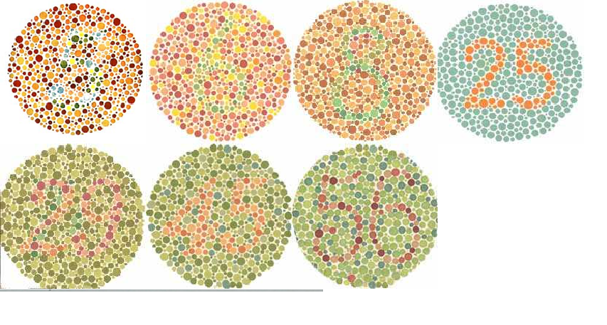
  1. FLUORESCENT – penetrants contain a green dye which fluoresces under ultraviolet light. This type of penetrant is considered the most sensitive. Fluorescent penetrants are considered more sensitive than visible dye penetrants because of their lower viscosity and better see-ability.


  1. VISIBLE DYE – penetrants contain a colored dye which is usually red and is visible in white light. This penetrant is the least sensitive because visible dye penetrants have a higher viscosity.


  1. DUAL SENSITIVITY – penetrants contain a combination of orange visible dyes and yellow fluorescent dyes. The test article is viewed under black light when increased sensitivity is required.


  1. METHOD OF EXCESS PENETRANT REMOVAL from the test surface :


Penetrants can be further categorized by one of the three methods used to remove the excess penetrant from the test specimen surface.


  1. WATER-WASHABLE – penetrants contain a built-in emulsifier and are self-emulsifying.    They are removable with plain water in a one step rinse process. The Water-Washable method is the least sensitive.


  1. POST-EMULSIFIED – penetrants require an emulsifier to be added in a separate step to make the penetrant removable with a water rinse. This is a two step removal process.


  1. SOLVENT-REMOVABLE – penetrants must be removed with a solvent. This is the most sensitive method.

Penetrant Removers

There are two basic types of removers and cleaners used to remove the excess penetrant from the test surface. The manufacturer designates the cleaner or remover that will be the best to use with a particular PT system.


  1. Solvent Cleaners and Removers


  1. Halogenated.
  2. Non-halogenated.
  3. Special Application


  1. Emulsifiers


  1. Lipophilic.
  2. Hydrophilic

Developers

Developers come in two basic forms, Wet and Dry. Depending on the manufacturer, developers can be substituted to enhance a PT system sensitivity.


  1. Dry Powder


  1. Non-aqueous Wet.


  1. Aqueous Wet


    1. Water Soluble
    2. Water Suspendable


    1. NON DESTRUCTIVE TESTING

      NON DESTRUCTIVE TESTING

CLASSIFICATION OF LIQUID PENETRANT – METHODS AND TYPES

METHOD A – FLUORESCENT PENETRANTS

Type 1            (Procedure A-1)        Water Washable Penetrant, Dry, Aqueous, or Non-aqueous

                                               Developer.


Type 2            (Procedure A-2)        Post emulsifiable Penetrant, Lipophilic or Hydrophilic

Emulsifier, Dry, Aqueous, or Non-aqueous Developer.


Type 3            (Procedure A-3)        Solvent Removable Penetrant, Solvent Remover / Cleaner,

Non-aqueous Developer.

METHOD B – VISIBLE PENETRANTS

Type 1            (Procedure B-1)        Water Washable Penetrant, Dry, Aqueous, or Non-aqueous

Developer.


Type 2            (Procedure B-2)        Post emulsifiable Penetrant, Lipophilic or Hydrophilic Emulsifier,

Dry, Aqueous, or Non-aqueous Developer.


Type 3            (Procedure B-3)        Solvent Removable Penetrant, Solvent Remover / Cleaner,

Non-aqueous Developer.


PROCESS SELECTION

The Selection of the best process depends upon:


  1. Sensitivity required or the smallest defect to be detected.
  2. Number of articles to be tested.
  3. Surface condition of the part being inspected.
  4. Configuration of the test specimen.
  5. Availability of water, electricity, compressed air and equipment.
  6. Suitability of the environment where the test will be performed.
  7. History of the test specimen:
    1. Manufacturing
    2. Overhaul or Repair
    3. In-Service
    4. Record of prior failures


  1. Governing Specifications and Codes.


Penetrant testing is successfully performed on Metals such as Aluminum, Magnesium, Brass, Copper, Carbon Steel, Stainless Steel, Titanium and most common alloys. It can also be used to test other materials including Glass, Ceramics, Composites, as well as some Plastics and molded Rubber products. Liquid penetrant testing is limited by its inability to detect discontinuities which are not open to the surface. Test surfaces must be clean and free of coatings and contaminants. The discontinuity must be open to the surface.


SPECIAL APPLICATION PENETRANTS

General

Penetrant materials are now biodegradable and safer for the environment. More recently, Dual sensitivity penetrants have given us the added capability of a fluorescent and visible dye mode in a single operation. Today, penetrants also come in gel, crayon, and magic marker forms for testing individual defects. They fit in your pocket.

Filtered Particle Penetrant


Extremely porous surfaces, particularly ceramics and components which have been metal sprayed, can be tested with Filtered Particle penetrants. These penetrants are available in fluorescent filtered particles only. The particles are large and suspended in a liquid penetrant. The properly sized and shaped particles are larger than the opening of the discontinuity which is to be detected. The particles will accumulate at the top of the discontinuity forming an indication.

Liquid Oxygen Penetrants

Special organic penetrants are available for the testing of liquid oxygen components. Liquid oxygen has an average temperature of -275°F below zero and will instantly burst into flames when contact is made with a petroleum based product. Therefore, penetrant materials used to test LOX components must not have a petroleum base. Penetrants designed for this purpose can be used with dry powder and aqueous developers.

High and Low Temperature Penetrants

Liquid penetrant materials have made significant advances in physical characteristics which allow testing to be performed in extreme temperatures, above and below the normal operating temperature range of 60°-125°F ( 16°-52°C ). Viscosity’s of the penetrants have been modified to the point where they are extremely efficient. High viscosity penetrants are available for the testing of hot welds. Low viscosity penetrants are available for testing in extremely cold environments.

EQUIPMENT,LIGHTING, PENETRANT MATERIALS, CLASSIFICATION CODES, AND SAFETY

Penetrant Equipment

There are two types of penetrant equipment; Stationary and Portable. Stationary equipment is found in shops and permanent buildings and is primarily used for testing large components and large quantities of test articles. The equipment is not mobile because of the usage of large dip tanks, wash stations, oven dryers, and developer chambers. The equipment may be arranged in any order to fit the process application.


Portable equipment is primarily used in the field for on site testing. Field portable equipment could consist of portable electrical generators, black lights, pump spray bottles, air compressors, and penetrant kits. Solvent-Removable Penetrant kits contain the necessary materials for testing and were designed specifically to be portable in the field. Solvent Removable PT materials come in aerosol spray cans which also makes them difficult to contaminate.


Water-Washable penetrants are mostly used with stationary equipment but can be used in the field in portable, pressurized, pump bottle dispensers. Three pump bottles are used. One bottle is for the penetrant spray application and one for the rinse water. A third pump bottle may be required for developer application. Portable air compressors can be used to apply the penetrant materials with pressurized air.


Post-Emulsified Penetrant systems are not considered portable because they require an extensive pressurized rinse water supply and the materials are more susceptible to contamination. The Post-Emulsified penetrant process also utilizes more steps in the test process. It is not economical and is more time consuming.


Penetrant equipment also consists of a variety of test panels, light meters, thermometers, and gages necessary to monitor the system performance and the testing process.

BLACK LIGHT

Black light equipment is required when performing fluorescent penetrant inspections. Black light is defined as electromagnetic radiation in the near ultraviolet wavelength range. UV light wavelength is measured in Angstroms ( A ) or Nanometers ( nm ) with 10 Angstroms equaling I Nanometer. The required wavelength of ultraviolet light is 365 nm or 3650 A. It is at this wavelength that the fluorescent dye in the liquid penetrant is activated. The dye absorbs the UV light, is energized, and emits a green fluorescent light at approximately 525 nm which is highly visible to the inspector.

A portable black light may be used with stationary or portable equipment. The black light equipment usually consists of a current regulating transformer, a mercury vapour arc bulb, and a deep purple, long wave, glass ultraviolet filter. The bulb and filter are contained in a reflector lamp unit and transformer and all electrical equipment is located inside the base of bulb.

Black light intensity is measured in microwatts per centimeter squared ( µW/cm2 ). For correct test results, the lamp must produce a minimum intensity of 1000 µW/cm2 for darkened areas or 3000 µW/cm2 for field inspections. It should be noted that black light intensity decreases as the light is moved further away from the test surface. Therefore, a specified distance is required to standardize the measurement. The standard measuring distance is 15 inches ( 38.1 cm ) from the front surface of the filter to the test object surface.

NON DESTRUCTIVE TESTING

NON DESTRUCTIVE TESTING

NON DESTRUCTIVE TESTING

NON DESTRUCTIVE TESTING

Bulbs and Filters

The deep purple filter on the black light is designed to pass only those wavelengths of light at 365 nanometers ( nm ) or 3650 Angstroms ( A ) which will energize the fluorescent dye in the penetrant. Longer wavelengths of the remaining visible light spectrum are filtered out. There are two kinds of filters, smooth and fluted. The smooth filter does not distort the light rays and allows them to pass without changing their path. The fluted filter diffracts the light rays scattering them over a wide area.


There are two types of mercury arc vapor bulbs used in black light equipment, the Spot bulb and the Flood bulb. The Spot bulb concentrates the rays of the light beam on a small area. The Flood bulb disperses the light rays over a wide area. If the Spot and Flood bulbs are rated at the same wattage or strength, the Spot bulb will read a higher intensity when measured because more light rays are concentrated in a smaller area. Both types of bulbs have an overheat switch located in the base of the bulb. The bulb will automatically shut down at a set temperature.


The intended usage of the black light unit and the intensities required for the inspection will dictate the best combination of bulb and filter. Fluted filters used in combination with Flood bulbs were designed for use during penetrant removal and are usually found in the rinse stations of PT stationary equipment. Spot bulbs coupled with Fluted filters are ideal for scanning large parts and large areas for indications. A Spot bulb used with a Smooth filter is best for the inspection of small areas or small components. This combination is best because it gives the maximum intensity on the test surface in the area of interest.


Measurement

Black light can be measured with a Spectroline DM-365X digital readout meter, UVP Black Ray J-221 mechanical gage meter, Spectroline DSE-100X digital readout, combination white and black light meter or an authorized equivalent. The light should be pointed in line with and centered over the light sensor at a distance of 15 inches ( 38.1 cm ) between the sensor and the light. The light can be moved back and forth or side to side until the highest reading is obtained. Black light intensity levels should be recorded on the PT Inspection Report and the Ultraviolet Light Intensity Log Sheet as required. A Light Intensity Log should be kept with the black light at all times.


The ultraviolet light intensity at the examination surface shall be measured:


  1. At least every 4 hours.
  2. Whenever the work location is changed.
  3. After changing a component of the unit such as a filter or bulb.
  4. After a UV light unit failure.

Equipment Operation

The full intensity of the lamp is not attained until the mercury vapor arc bulb is sufficiently heated. At least a 5 minutes warm-up time is required for the bulb to reach the required arc temperature. Should the bulb go out for any reason, intentionally or accidentally, the unit will not restart if it is immediately turned back on. You must always allow a 10 to 20 minutes cool down period before a restart is attempted.


Once turned on, the lamp should be left on during the entire working period. Frequently switching the light on and off, for whatever reason, shortens the life of the bulb significantly. Material is removed from the bulb electrode at each start. A single start is the equivalent of several hours of burning time. A stable electrical source should also be used. Line voltage drops will cause the lamp to extinguish or go out, requiring a restart. Line voltage increases will drastically reduce bulb life.


Mercury vapor arc black light bulbs fade proportionally with operation time. Black light intensity can fade more than 50% before the bulb burns out. Light intensity measurements should be recorded every 4 hours on an Ultraviolet Light Intensity Log sheet. The log sheet should be reviewed periodically to track the bulb intensity for fading trends. A dirty, heavily scratched, or cracked filter can reduce black light intensity. Filters should be cleaned on the inside and the outside and checked before each use. Cracked or excessively scratched filters should be replaced immediately. Cracked lenses expose white light emitted by the mercury vapor arc bulb and are dangerous to the inspector. NEVER look directly into an operating mercury vapor arc bulb without a filter.


Eye Adaptation

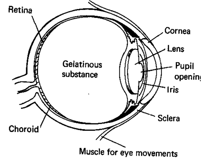
A minimum of 5 minutes should be waited after entering a darkened area and before inspection begins. This is called an eye adaptation period and will allow the pupils of the eye to expand and adjust to the darkened condition. A short period for eye reorientation should also be allowed after looking directly into an operating black light. Although it is not harmful, this may cause the eyes to become cloudy due to the cornea of the eye fluorescing. Do not wear glasses with photo-chromatic or light sensitive lenses while performing any PT inspections. UV light will tend to darken the lenses.

Darkened Area Inspection

To achieve maximum black light intensity, fluorescent penetrant inspections should be performed in a darkened area. A maximum white light intensity of 2 ft-candles or 22 lux ( lx ) is allowable in a darkened area or booth. All attempts should be made to darken the area where a fluorescent penetrant inspection will take place in the field. Even if you can not darken the area to 2 ftc ( 22 lx ) or below, darken the area as much as possible. This can be done utilizing a black blanket, hood, or a portable enclosed booth. White light penetrating the darkened booth, in sufficient quantity, absorbs the filtered ultraviolet light. This reduces the intensity of the ultraviolet light, the see-ability of any indications, and the sensitivity of the inspection. It is for this reason that every attempt should be made to darken the test area as much as possible. White light should be measured before each fluorescent penetrant inspection, whether performed in the field or in a darkened area. A white light measurement is taken before performing a fluorescent penetrant examination to determine the minimum black light intensity requirements.

Black Light Usage


The black light will always be used four times during a fluorescent penetrant inspection. The inspector will verify that the Pre-cleaning (Step 1) and Post-cleaning (Step 6) operations have been thorough and complete by scanning the test surface with the black light. Excess Penetrant Removal (Step 3) and the Interpretation and Evaluation (Step 5) of indications will also be performed with the test surface illuminated with black light.

TROUBLESHOOTING AND REVIEW

A bulb and lens filter combination used for a penetrant test must insure the minimum required light intensity is projected on the test surface. The rule of thumb is the highest intensity possible is the most desirable.


Light intensity to be checked every 4 hours, when changing job sites, after a black light unit failure, or after changing a bulb or filter. Minimum intensity should be:


  1. 1000 µm/cm2 @ 15 inches (38.1 cm) for darkened areas 2 ftc(22 lux) or less of white light.


  1. 3000 µw/cm2 @ 15 inches (38.1 cm) for field inspections or areas of white light greater than 2 ftc (22 lux).


Causes for black Light failure:


  1. a) Power disconnected.


  1. b) Line voltage fluctuation.


  1. Low Voltage – Will cause Bulb to turn off.
  2. High Voltage – Will cause bulb to burn out.


  1. c) Overheat – Thermal switch cutout or fan inoperative.


  1. d) Bulb burned out


Causes for low intensity output:


  1. a) Dirty, excessively scratched or cracked lens


  1. b) Bulb fading


  1. c) Excessive ambient white light.


  1. d) Light meter out of calibration.


Procedure to check operation or bulb integrity after a failure:


  1. a) Turn off unit and allow 15 minutes for unit to cool down.
  2. b) Check power to the unit, turn the unit on and allow 5 minutes for bulb warm up.
  3. c) Measure light intensity and check fan operation if so equipped.
  4. d) Replace bulb if inoperative or intensity is below minimum requirements.
  5. e) If bulb is still inoperative, replace unit.

WHITE LIGHT

Requirements


The amount of visible white light necessary to perform a visible dye penetrant inspection is measured in Lux (Lx) or Foot-Candles (ftc). 11. White light intensity of 32.5 ftc (355 Lux) at the examination surface for a field inspection and 100 ftc (1076 Lux) minimum for a bench examination.


White light is necessary throughout the inspection process but is very important during Interpretation and Evaluation (Step 5). Elevated white light intensities greatly increase the contrast of the red penetrant indications against the white developer background. This makes the indications easier to see and reduces eye strain and eye fatigue.

Measurement

White light can be measured using a digital light meter, or an authorized equivalent. When measuring light intensity, the light sensor or meter should be placed on the surface to be inspected in a configuration reproducing the normal viewing of the test specimen by the inspector. White light levels should be measured before each inspection and recorded on the inspection report.

PENETRANT TESTING MATERIALS


Penetrant materials are often restricted to specific groups. The established groups can use a combination of penetrant materials to obtain the best results.


  1. WATER-WASHABLE PENETRANTS – contain an emulsifying agent which makes them easily removable in one (1) step with a water rinse or wash. They were specifically designed for ease of removal from rough surfaces such as castings, for testing large parts, large quantities of parts, and parts with complicated shapes. Penetrant removal is extremely critical because the penetrant is easily over-washed. This type of penetrant can be obtained in either a fluorescent or visible. dye.


  1. POST-EMULSIFIABLE ( PE ) PENETRANTS – are high sensitivity, oil based, visible, or fluorescent penetrants that are not soluble in water. These penetrants must be treated with an emulsifier before they can be removed by a water rinse. The emulsifier is added separately to make the penetrant water soluble and then rinsed off. This procedure is referred to as a two (2) step removal process. PE penetrants are not as easily over-washed as Water-Washable penetrants. They are mostly used in stationary equipment and are not considered portable.


  1. SOLVENT-REMOVABLE PENETRANTS – are oil based penetrants that also do not contain an emulsifying agent. They are identical to PE penetrants except they are manually removed by wiping the test surface with a solvent dampened cloth or rag. These penetrants are specifically designed to be portable and come in pressurized spray cans. They are available in visible or fluorescent types.


  1. EMULSIFIERS – are applied to a penetrant coated surface and makes the resultant mixture removable by a water rinse or wash. Emulsifiers have low penetrating characteristics so they will not remove indications from the test specimen surface. There are two (2) kinds of emulsifiers. Lipophilic emulsifiers quickly diffuse into the penetrant on the test surface in 1 to 4 minutes much like a solvent. Hydrophilic emulsifiers react more slowly. They are commonly sprayed on the test surface in a water mixture. The excess penetrant is removed with the assistance of a scrubbing action water spray like a detergent. Emulsifiers only come in bulk containers and are not portable.
  2. SOLVENT REMOVERS – are designed to be used with specific penetrants. Typical removers are organic or man-made petroleum based chemicals. They come in bulk containers for use in spray guns or portable aerosol spray containers. They are typically used 3 times during a penetrant test for pre-cleaning, excess penetrant removal, and post-cleaning.
  3. DRY DEVELOPERS – are a fluffy, absorbent, white powder that is used in both fluorescent and visible dye penetrant tests. These developers are not mixed with anything and applied in a dry state by dusting. They are only available in bulk and are primarily used with stationary equipment such as dust chambers. They can also be applied manually with a squeeze bulb. Dry developers are very sensitive. They are excellent for use on parts with rough surfaces and


complicated geometries and are easily removed. Dry powder developers are rarely used in the field and not considered portable.

  1. AQUEOUS WET DEVELOPERS – are a mixture of water and white developing powder. Water is used as the delivery vehicle to apply the developer to the test surface. Application is by dipping or spraying. There are two (2) kinds of Aqueous Wet developers. Water Soluble is a mixture of water and powder where the powder dissolves in the water. Water Suspendable

developer keeps the powder particles suspended in the water. The particles do not dissolve in the water. Water Suspendable developer is considered the least sensitive of all the developers. Aqueous developers are best used on parts with smooth surfaces and simple shapes.

  1. NON-AOUEOUS WET DEVELOPERS – differ from wet developers because, the powder particles are mixed with a quick drying solvent. The powder is suspended in the solvent and is applied to the test surface by spraying. These developers are most commonly used in aerosol spray cans which makes them portable. They can not be used in open tanks because the solvent base evaporates too quickly. The use of solvent as a delivery vehicle is what makes Non-aqueous wet developers the most sensitive for the detection of extremely small and tight defects.
  2. LIQUID OXYGEN ( LOX ) COMPATIBLE MATERIALS – must be used when testing parts that will be in contact with either liquid or gaseous oxygen. These materials are specifically designed to be inert when in the presence of LOX.
  3. FILTERED PARTICLE PENETRANTS – are used for testing porous surfaces, such as unfired ceramics and thermal sprayed metal and coatings. They use large fluorescent particles which gather at the top of a discontinuity to form an indication rather than penetrate the into the discontinuity cavity.

Corrosive Contents

Penetrant materials must be designed with a low sulfur and halogen content to avoid harmful effects on the test articles. These chemicals will promote corrosion and in some cases hydrogen Embrittlement. Stainless Steels are especially susceptible to corrosion when exposed to Chlorine and Carbon Steels to Sulfur. Titanium is extremely susceptible to Embrittlement when in contact with Halogens. These harmful chemicals can be found in small amounts in all the penetrant materials and are limited to 1% by weight of content.


Penetrant materials can be used in a variety of combinations. Most materials are available in either bulk quantities or pressurized spray cans. All penetrants are available in either visible or fluorescent types. The flow chart below illustrates the different material combinations. However, it can not be overstated that care should always be taken to assure that the manufacturers specifications and company procedures are closely followed. The manufacturer designed the material groups and designates the groups and combinations that will give the best test results. It is the responsibility of the Saudi Aramco NDT Level III to authorize a compatible material group for use or a suitable substitute material if required.

LIQUID PENETRANT MATERIAL FAMILIES

Penetrant Material Selection

A family or group of penetrant materials will always include a penetrant, cleaner or remover, and developer. The manufacturer designates the compatible family and group. Substituting products from the same manufacturer is not allowed unless the manufacturer recommends it. These are penetrant materials that are designed to work well together and will when selecting your consumables before a PT , NEVER substitute penetrant materials made by different manufacturers in a family. NEVER substitute penetrant materials from different groups either. This is especially true when using fluorescent penetrant materials. Certain chemicals may degrade the brightness of the penetrant indication. A penetrant test procedure using substitute materials from different manufacturers is not valid unless qualified by a certified NDT Level III.

Part Numbers & Batch Numbers

Some material part numbers may have different letters or numbers at the end of the part number. This indicates a revision has taken place. The manufacturer may have changed an ingredient in the material or possibly the propellant in the spray can. It should be confirmed that the product is still compatible with the family. Batch numbers are supplied by the manufacturer to provide traceability from the manufacturer to the inspection test and usually indicate the date the material was manufactured. Batch numbers are usually found somewhere on the material containers stamped in ink. If they are not stamped on the containers or aerosol cans, they may be found on the box the cans were shipped in or the certificate of compliance ( C of C ) received with the shipment. The penetrant batch number will be recorded on the inspection report along with the part numbers of all the penetrant materials used for the test.

Batch Numbers

Batch numbers are supplied by the manufacturer to provide traceability from the manufacturer to the inspection test and usually indicate the date the material was manufactured. Batch numbers are usually found somewhere on the material containers stamped in ink. If they are not stamped on the containers or aerosol cans, they may be found on the box the cans were shipped in or the certificate of compliance (C of C) received with the shipment. The penetrant batch number will be recorded on the inspection report along with the part numbers of all the penetrant.


LIQUID PENETRANT MATERIAL FAMILIES

A-1 Fluorescent Water Washable (Group IV)

SHERWIN HM-420, HM-430,

HM-604

Water D-90G, D-100, D-100NF
ARDROX P133D or P134D Water 9D1B, 9D4A, 9D6/D495A,

D499C

MAGNAFLUX ZL-56 or ZL-67 Water ZP-4B or ZP-9F

B-I Visible Dye Water Washable (Group III)

SHERWIN DP-50 or DP-51 DR-60 or Water D-90G, D-100, D-100NF
ARDROX 996/P303A Water 9D1B, 9D4A, 9D6/D495A,

D499C

MAGNAFLUX SKL-WP SKC-S or Water ZP-4B, SKD-NF, SKD-S2

A-3 Fluorescent Solvent Removable (Group VII)

SHERWIN RC-65 or RC-77 DR-60 or DR-61 D- 100 or D-100NF
MAGNAFLUX ZL-27A SKC-NF/ZC-7 or SKC-S SKD-NF/ZP-9 or ZP-9F
ARDROX 996/P300A 9PR50, 9PR551, K410C,

PR1

9DIB, 9D6/D495A,

D499C

CROWN 1032 1031 1033

B-3 Visible Dye Solvent Removable (Group I)

TURCO Dy-Chek Remover #3 NAD
CROWN 1075 1071 1079
MAGNAFLUX SKL-LO or SKL-SP SKC-NF/ZC-7 or SKC-S SKD-NF/ZP-9 or SKD-S2
SHERWIN DP-40 DR-60 or DR-61 D-100 or D-100NF
ARDROX 996/P300A 9PR50, 9PR551, K41OC,

PRl

9D1B, 9D6/D495A,

D499C

CASTROL 222  

S – 72

LD-3
JOHNSON and ALLEN JAP JAC or JAC II JAD


SAFETY

Liquid Penetrant Materials and Usage

The materials used in Liquid Penetrant testing can be harmful to the test operator or the component under test. Generally speaking, it is a relatively safe method of testing unless it is abused or certain simple precautions are not taken. Although flash points of penetrants and emulsifiers average above 200°F, they are still considered flammable, especially when used in open dip tanks. Liquid Penetrant materials should NEVER be used near open flames, electrical arcing such as welding, or exposed to extremely high heat sources above their operating temperature range.


Vapors from the penetrants and emulsifiers are basically harmless to the test operator. Prolonged skin contact can cause skin rashes and should be avoided. Rubber gloves and a rubber protective apron should be worn when possible. Safety glasses should ALWAYS be worn to avoid eye contact safety shoes with steel toe tips should be standard attire. Handling parts coated with penetrants are slippery and can be easily dropped.


Solvents can be dangerous because of their high volatility, low flash points, high flammability, and toxic vapors. ALWAYS use in a well ventilated area with good air circulation. Breathing the vapors can cause dizziness. Enclosed areas will require filtered breathing apparatus such as a respirator to be worn. The solvents should NEVER be used near open flames or potential electrical arcing.


Non-aqueous developers also contain the same solvents used for cleaning and penetrant removal, in addition to developer powder. The same precautions should be observed as when using the solvents for cleaning. Although developer powders are considered nontoxic, excessive inhalation should also be avoided.

Storage and Handling

Care should be exercised during storage, handling, and transporting of penetrant materials. Storage should be in dry areas, preferably at room temperatures. Exposure of materials to direct sunlight and extreme temperatures outside of their normal operating range, even in sealed containers, can cause contents to separate permanently or degrade their sensitivity. Fluorescent penetrants are susceptible to dye separation and fading. Non-aqueous developers tend to coagulate and get lumpy in the aerosol can. Solvent removable penetrant materials in aerosol cans are susceptible to exploding in temperatures above 120°F ( 50°C ), regardless of their flash point. The propellants in the aerosol cans expand proportionally with increases in heat.


Testing Precautions

Any of these materials may be harmful to the test article if plastics or rubbers are involved. If possible, a sample test article should be inspected first to determine if the penetrant materials will damage the test article. Some rubbers expand when in prolonged contact with penetrants and some plastics may melt or become permanently stained. Performing Liquid Penetrant testing on assembled parts with gaskets should be avoided. If possible, the component should be disassembled and done in individual pieces. This also provides accessibility to flange mating surfaces.

Equipment

Black light ultraviolet emissions are harmless to the skin and eyes provided the equipment is maintained. The black light will not cause sunburn and is not harmful if shined in your eyes as long as the proper filter is in place. However, light emission from an unfiltered mercury vapor arc bulb is extremely harmful to the human eye and will cause sunburn.

SURFACE PREPARATION

Surface Cleaning

Pre-cleaning is the very first step when performing a liquid penetrant inspection. The effectiveness of a penetrant test is based upon the ability of the penetrant to enter surface discontinuities. Contaminants including grease, carbon, dirt, scale, varnish, oil, oxides, corrosion and water must be removed from the test surface and the discontinuity cavity. All paint, plating, core material is the most common contaminant, the test surface should also be thoroughly dry before the penetrant is applied to the surface.


Liquid penetrant placed on the surface of a test specimen does not only seep into a flaw cavity, it is pulled into them by capillary action. Proper cleaning is essential to liquid penetrant testing for three reasons :


Contaminant will prevent the penetrant from wetting the surface properly and block the entrance of penetrant into the flaw cavity. Discontinuities must be open to the surface.

If all traces of penetrant materials are not removed after the test, they may have a harmful effect on the test specimen. Sulfur and halogens will promote corrosion and in some cases hydrogen Embrittlement in some alloys.

Acids, water and salts can affect the sensitivity of the penetrant. This is specially true for fluorescent penetrants.


A visual inspection will always be accomplished before, during and after the pre-cleaning procedure. The purpose is to select the proper pre-cleaning method, assure that the test surface is contaminant free, identify gross discontinuities and identify any areas of interest where an indication will be expected to occur. A contaminant is defined as any foreign material on the surface that will prevent the penetrant materials from performing their intended functions. An area of interest is defined as any irregularity on the surface where a penetrant indication will be expected to form.


There are several contaminant removal methods to choose from. The selection of the proper method depends on the type of the contaminant you wish to remove and the type of material you wish to remove it from. The ideal method selected will remove the contaminants and not disturb or damage the surface of the material to be tested.


  1. DETERGENT SOLUTIONS : are a common means of pre-cleaning to remove contaminants and residual chemical films from the component surface. Initial pre-cleaning is for removal of dirt and soil. Some industrial detergents will also remove oil and grease. Secondary pre-cleaning is for removal of residual chemicals or oily films after paint stripping, acid or alkaline cleaning or an etching procedure has been accomplished. Detergent cleaning is accomplished by scrubbing with a soft bristle brush, rinsing and drying.


  1. STEAM CLEANING : is performed with a heated degreasing or detergent solution applied in a high pressure spray. It is particularly adaptable to the cleaning of large or bulky articles which can not be handled easily.


  1. SOLVENT CLEANING :   may be applied by flushing the test surface with spray, a wipe on and off technique or immersed in a dip tank. It is the most commonly used method for pre-cleaning and must be performed in a well ventilated area due to the toxicity of the vapors.


  1. ACID & ALKALINE CLEANERS : are used for corrosion, rust and scale removal. They are usually applied by dipping or brushing and allowed to dwell on the surface for a certain period of time and rinsed off. The manufacturers instructions should be closely adhered to or this method could damage the part. An acid or alkaline cleaning is always followed by a detergent washing or solvent flushing to assure the test surface is totally free of residual chemicals.


  1. VAPOR DEGREASING : is the most desirable method for removal of oil, grease and similar contaminants. However, certain alloys such as titanium have an affinity for specific elements used in vapor degreasing which may cause structural damage. Vapor degreasing is performed by dipping the part in a tank of degreasing vapor and usually accompanied by heat. When allowed to soak in the vapor for a sufficient time, the vapor will penetrate into the discontinuity openings. This makes vapor degreasing a very through cleaning method.

(In Next Article We Discuss the Remaining Topics of Non Destructive Testing ( Liquid Penetrant Testing)….)


NON DESTRUCTIVE TESTING


NON DESTRUCTIVE TESTING (NDT):

LIQUID PENETRANT TESTING


INTRODUCTION TO NON DESTRUCTIVE TESTING:

Non destructive Testing NDT  includes a variety of testing methods. Non destructive testing NDT is defined as examination of a material or a component to determine the physical soundness of the specimen without damaging, altering, or impairing its usefulness.


Non destructive Testing NDT  is one of many tools used to assure the quality and reliability of a product during manufacture and while it is in-service. The primary objective of any Non destructive Testing NDT method is to find defects before they become large enough to cause expensive repairs or a component failure. Industrial applications include all levels of material usage.


  1. Raw Materials.
  2. Fabrication processes.
  3. Finishing Processes.
  4. In-Service.
  5. Overhaul
    NON DESTRUCTIVE TESTING

    NON DESTRUCTIVE TESTING


Raw materials are examined before fabrication begins to avoid manufacturing or repairing a component with defective material. Manufacturing productivity is increased by avoiding unnecessary delays.’ Non destructive Testing NDT is accomplished after all fabrication and finishing processes to assure a manufacturing procedure has not uncovered a defect in the material or damaged the component. These precautions reduce wasted manpower and unnecessary component failures in the field. Statistical analysis has proved conclusively that a well planned and wisely implemented Non destructive Testing NDT quality control program is safer and far more economical than a program consisting of build now and fix later.


The most common Non destructive Testing NDT methods are:


  1. Visual Examination (VT).
  2. Penetrant Testing (PT).
  3. Magnetic Particle Testing (MT).
  4. Eddy Current Testing (ET).
  5. Ultrasonic Testing (UT).
  6. Radiographic (RT)

LIQUID PENETRANT TESTING

Introduction to LIQUID PENETRANT TESTING

Liquid Penetrant testing is capable of revealing only those discontinuities which are open to the surface. All discontinuities which are subsurface will require an alternate Non destructive Testing NDT method for detection. Radiography and Ultrasonic testing are most commonly used to detect subsurface discontinuities while Liquid Penetrant and Magnetic Particle testing are most commonly used to detect surface discontinuities. A discontinuity or flaw is defined as an interruption in the normal configuration of a component. If a discontinuity or flaw will interfere with a components’ usefulness, it is then called a defect.


Liquid Penetrant is an improvement over visual inspection. Penetrant testing increases the sensitivity of flaw detection by highlighting a discontinuity for easier visual detection. The discontinuity is magnified in size by an indication produced on the surface being examined as a direct result of the test. By increasing the dimensions of the surface defect, flaws previously undetectable with the naked eye become visible. Usage of highly contrasting colors in the penetrant materials also provides increased see-ability. Penetrants are usually bright red or fluorescent green. Developer is always white to highlight the color of the penetrant.


The indication is larger than the actual discontinuity


The primary purpose of PT is to make discontinuities highly visible for speedy detection and interpretation. Visual inspection of large components or large quantities of test articles is neither efficient nor economical and relatively small defects can not be detected with a high degree of confidence. Liquid Penetrant testing provides for


accelerated component scanning speeds with an increased confidence level for the detection of small defects. Fluorescent liquid penetrant testing is capable of detecting an indication 0.01 inch ( 0.254 mm ). When the correct penetrant materials are used and the procedure followed properly, an indication 0.03 inch ( 1/32″ or 0.76 mm ) is the standard size indication which should be confidently detected.

Testing can be performed on a wide range of materials including metals, composites, glass, ceramics, plastics, and rubbers. Liquid Penetrant testing is the most effective and works the best when used on smooth and nonporous materials. Porous materials can be tested with special penetrant materials that are specifically designed for this purpose.

ADVANTAGE:

Liquid Penetrant Testing (PT) is the most widely used Non destructive Testing NDT inspection method. It is very inexpensive, does not require an extraordinary amount of training, and is more sensitive than a visual inspection alone. It provides direct indications produced by the discontinuity. The average penetrant test should only take approximately one hour to perform. As compared to the other NDT methods, it is one of the relatively slower methods because it will not yield instantaneous results. The primary advantage of PT is its versatility because it can be used to test a variety of materials at a low cost.


Some of the other advantages of PT are its ease of application, ability to test irregularly shaped components with complex geometries, field portability, and simplicity. The PT test procedure consists of six basic steps that follow a logical sequence and are relatively simple to perform. All PT tests include the use of a liquid penetrant, some type of cleaner or remover, and a developer. The application of the materials may vary, the equipment requirement may differ, additional steps may be inserted in the more complicated methods, but the six basic procedure steps will always remain the same.


The six basic steps to a liquid penetrant test are:


  1. Surface Preparation
  2. Penetrant Application
  3. Removal of the excess penetrant
  4. Developer Application
  5. Inspection
  6. Post-cleaning


One of the biggest traps associated with PT is attitude. The tendency is to oversimplify the method. As we will find out in the remainder of this course, PT requires technique and experience to interpret and evaluate indications as well as to recognize when something is going wrong with the test.

DISADVANTAGE:

PT has a limited operational temperature range. To be effective, testing should be performed when the temperature of the surface to be tested is between 60°-125°F ( 16°- 52°C ). The surface temperature of the test article will directly affect the speed the penetrant will work. There are special penetrants available which are designed for testing outside the operational temperature range.


The success of any PT test depends on the visibility of the indications. We already know that penetrant testing is only capable of revealing discontinuities open to the surface and the test surface should be clean, dry, and smooth. Anything that could block the penetrant from entering the opening of the discontinuity must be removed. Contaminants that must be removed includes : dirt, rust, oil, grease, scale, water and acids. The most common contaminant encountered is water. Water is heavier than liquid penetrant and has a higher specific gravity, therefore, penetrants will tend to float and bead up on the surface of a test article that is wet. All paint and corrosion inhibitor coatings must also be removed.


Surface preparation prior to a PT test by the use of any method that mechanically removes material such as sanding, grinding, or sand blasting is not recommended. The use these surface preparation methods could possibly close the discontinuity opening. Chemical removal methods are preferred for surface preparation but they take time. We can now see that careful and sometimes extensive surface preparation is a limitation to PT.

NON DESTRUCTIVE TESTING NDT

NON DESTRUCTIVE TESTING NDT


BASIC PROCEDURE:

The six basic steps of a Liquid Penetrant examination are illustrated below as follows:


Step 1 – The test surface is pre-cleaned and a pre-visual inspection performed to identify

areas of interest where an indication will be expected to form.


Step 2 – Penetrant is applied and Dwell Time / Penetration Time is allowed for the penetrant

to seep into the discontinuity opening.


Step 3 – The excess penetrant is removed from the test surface.


Step 4 – Developer is applied. Time is allowed for the penetrant to be drawn out of the

discontinuity opening and for an indication to form. Development Time.


Step 5 – The test surface is visually examined and indications are Interpreted to determine

their cause and Evaluated against specifications to determine if the discontinuity will

interfere with the usefulness of the test specimen.


Step 6 – The test surface is post-cleaned to remove the remaining penetrant materials to

prevent corrosion. A post-visual inspection is performed to assure the test specimen

has not been damaged during the test.

BASIC THEORY AND PRINCIPLES

NON DESTRUCTIVE TESTING

NON DESTRUCTIVE TESTING

Capillary Action

Liquid Penetrant testing is a nondestructive means of locating surface discontinuities based on CAPILLARY ACTION. This refers to the natural ability of a liquid to be pulled or drawn into a small opening. The liquid penetrant consists of two parts. The penetrant consists of an oil based “Liquid Vehicle or Carrier” which must transport the “Dye content” in suspension and into the discontinuity opening. The properties of liquid penetrant materials are tailored to maximize this ability. Capillary action is employed twice during the PT test procedure.


In the Liquid Penetrant test procedure, the surface of the test specimen is thoroughly cleaned and dried. The liquid penetrant is applied to the surface of the specimen and sufficient time is allowed for the penetrant to enter any openings of surface discontinuities. CAPILLARY ACTION assists the penetration into the discontinuity openings. The excess penetrant on the test surface is removed, leaving the penetrant inside of the discontinuity cavities or openings. CAPILLARY ACTION is again employed when a coating of developer powder is applied to the test surface. The developer acts as a blotter to draw penetrant out of the discontinuity cavity forming a highly visible indication. The indication is then evaluated and the results compared to an acceptance standard.


If the discontinuity is small or narrow, as in a crack or pinhole, capillary action assists the penetration. Capillary action of a penetrant increases as the size of a discontinuity opening decreases. This is why penetrant will work on the underside of a test component. Penetration does not depend on gravity. The cohesive and adhesive properties of the penetrant and the material of the component under test will promote or hinder capillary action. The forces of cohesion and adhesion are described as the molecular attraction of the liquid and the test surface to themselves and between each other. Cohesion is defined as the forces of attraction of like molecules to each other, whereas, Adhesion is the attraction of unlike molecules to each other.

Penetrant enters the discontinuity at the 6 o’clock position

We can determine the capillary action of any liquid by witnessing the height or depression of capillary rise. A small diameter tube called a capillary tube is placed in a container of penetrant for a specified amount of time. The height of the liquid rise in the tube is the point where the liquids adhesive, cohesive, and surface tension forces are all equalized. The capillary tube represents a discontinuity opening.

Capillary Action in Different Size Openings

SURFACE TENSION AND CONTACT ANGLE

SURFACE TENSION and CONTACT ANGLE are the terms used when referring to the working properties of a liquid penetrant. A liquid with a high cohesive force has high surface tension and will cause a liquid to form a droplet or bead. This will cause the liquid to stay in a round droplet formation and will not allow the liquid to spread out into a thin film. Mercury is an example of a liquid with an extremely high surface tension.

Surface Tension can be determined by measuring the Contact Angle of the penetrant in relation to the way the penetrant lays on the test surface. The contact angle of the penetrant in relation to the test surface must be 90 degrees or less. A good penetrant will have a contact angle of 5 degrees or less. The ideal penetrant will have a low enough surface tension to be able to spread out into a thin continuous film without breaking up. This ability to provide a complete and continuous coverage of the test surface is referred to as wetability. Wetability is totally dependent upon Surface Tension and Contact Angle.

The penetrant must completely coat the test surface to assure that any discontinuity opening is covered. The penetrant, obviously, has no chance to enter an opening if it does not cover it. If the penetrant beads up on the test surface after penetrant application, something has gone wrong with the test and the test surface must be cleaned and the test started over. Water or solvent not thoroughly dried on the test surface is the most common causes of this happening. Grease or oil left on the test surface will also cause this condition.

Cohesive and Adhesive forces are affected by the material the test specimen is made of. and the condition of the test surface. Surface Tension of a penetrant is naturally higher on steel as opposed to aluminum. The same can be said about a smooth surface condition as compared to a rough surface. Although a smooth surface is the best for a PT test, a shiny or polished surface will cause a significant increase in surface tension and a higher contact angle. High surface tension makes it more difficult for the penetrant to enter any openings.

Prices depend on Financial Risk Management etc. We can hire can even in the most of threat of numbers and changed my assignment. Of Management courses.