API 510 Questions | API Training Institute in Trichy

API 510 Questions

1.A PQR was qualified in SG position using a new welder. But production welding is to be done by   the same welder in 3G position. Which of the following are applicable as a minimum?

  • Both procedure and welder shall be re-qualified in 2G position.
  • The qualified procedure can be used, only welder needs to be re-qualified in 3G position.
  • The welder is qualified, but the procedure needs re­-qualification.
  • Both procedure and welder need not be re-qualified.

2.A procedure is required with preheat temp = 2S0oF. Two WPS were made based on this PQR. All other parameters being same WPS (A) showed preheat temp = 280°F and WPS (B) showed preheat temp = 140°F, will you:

  • Reject (A) & (B)
  • Accept (A) only
  • Accept (B) only
  • Accept both

3.In a certain PQR for SMAW, the electrodes used for all passes were of AWS classification (E7018). Corresponding WPS also showed filler materials as E 7018. Now the manufacturer proposes to change the filler material in WPS to E 701S. Will you ask manufacturer to:

  • Quality new PQR with E 7015 electrodes.
  • Revise only WPS showing the change from E 7018 to E7015 and submit WPS as a new    revision.
  • Revise only the PQR showing the change and resubmit for approval.
  • Revise both WPS and PQR showing the change and resubmit for approval.

4.A PQR in GTAW process was qualified with PWHT with A 516 grade 70 materials, ¾” thick. The thickness for production welds is 1.0”, but without PWHT. The manufacturer claims that same PQR will be O.K. What is your assessment?

  • It qualifies required conditions hence no new PQR is required.
  • It qualifies thickness but not It does not qualify “No PWHT” condition, hence new PQR is   required.
  • It qualifies “no PWHT” condition, but not thickness. New PQR is required.
  • It does not qualify both thickness as well as “No PWHT” – condition, hence new PQR is    required. ­

5.For 515 grade 60 material, the following results were obtained for two tensile test specimen during   a PQR qualification.

Specimen T1: failed in B.M. at 57,400 psi

Specimen T2: failed in weld metal, at 59,500 psi

Your assessment is:

  • PQR test is OK since both are within acceptance criteria
  • PQR test is rejected as both T1 and T2 are not within the acceptance criteria
  • PQR in rejected because T1 is OK but T2 has failed
  • PQR in rejected because T1 is failed thoughT2 is OK

6.A procedure is qualified with Base metal THK. = 20mm. Two WPS were made based on this PQR. Other parameters being same, WPS (A) showed Base Metal Thk. = 38 mm and WPS (B) showed Base Metal Thk. = 6mm.

Your assessment is:

  • Reject (A) & (B)
  • Accept (A) only
  • Accept (B) only
  • Accept both

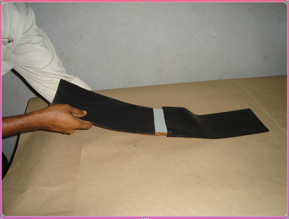
7.A welder has made 25 SMAW groove welds, but the guided bend test for the welder’s qualification was never performed. In order to avoid cutting out all of the production welds made by this welder, which of the following minimum steps would be taken to validate the qualification?

  • Radiograph the welder’s first production weld and accept the qualification based on acceptable weld quality by radiography.
  • There is no alternative to qualifying a welder by the guided bend test.
  • Have the welder prepare a test coupon and have the bend test done on that. If bend test is okay,    accept the welds already made.
  • Radiograph all 25 welds, regardless of the governing specifications for sample selection.

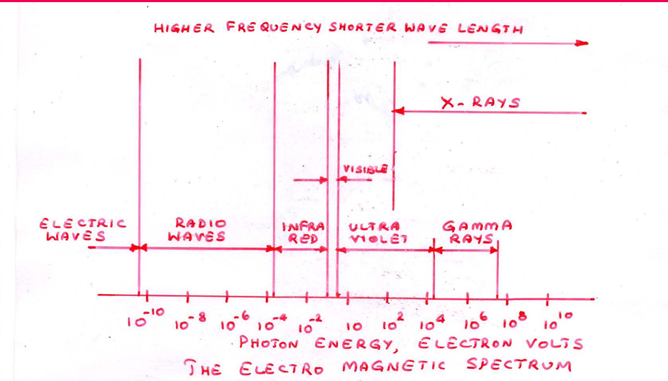
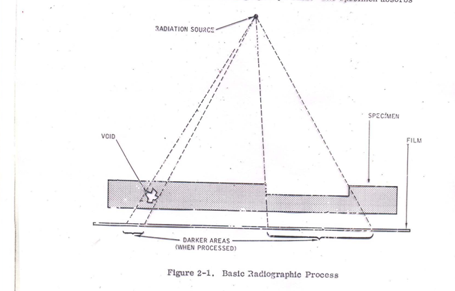
8.In a radiographic examination of butt weld (Thk= 3.5 in.) the Geometric un-sharpness shall not exceed?

  • 0.02″
  • 0.04″
  • 0.03″
  • None of above

9.Select suitable Hole Type (Source Side) penetrameter for following weld joint:

Base Mertal Thk. = 7/8”

Backing Strip Thk. = 3/16”

Weld Re-enforcement Thk. = 1/8”

  • No. 20
  • No. 25
  • No. 30
  • None of the above

10.If type of penetrameter in above question is changed to wire type what shall be the wire designation (wire diameter In Inch)?

  • 0.025 dia. (No.10)
  • 0.016 dia. (No. 8)
  • 0.032 dia. (No.11)
  • None of the above

11.For steel plates and welds to be checked by LPI what shall be the penetration time for the Penetrant?

  • 10 min for weld, 5 min for plate
  • 5 min for both
  • 10 min for both
  • 5 min for weld, 10 min for plate

12.After applying the developer the examiner checked four welds for surface defects after following period, weld A after 5 minute, weld B after 10 minutes, weld C was checked after 30 minutes and welds D after 65 minutes. Which of the welds were checked wrongly?

  • Weld A and B
  • Weld C and D
  • Weld D only
  • Weld A and D

13.For MT examination by Prod Technique the spacing between prods shall be between?

  • 4 inch to 12 inch
  • 4 inch to 10 inch
  • 3 inch to 10 inch
  • 3 inch to 8 inch

14.Calculate estimated inspection period for external and internal inspection for a vessel whose remaining life is estimated as 12 years?

  • Internal = 6 years, external = 10 years
  • Internal = 6 years, external = 5 years
  • Internal = 5 years, external = 10 years
  • None of the above

15.As per WPS the material used is SAS16 Gr.70 and the electrode used is E-7018. What are the P. No. and F No.?

  • 1 and 4
  • 4 and 1
  • 2 and 4
  • 4 and 2
­Q. NO. ANSWER
1 D
2 B
3 B
4 B
5 C
6 D
7 A
8 B
9 B
10 D
11 D
12 D
13 D
14 B
15 A

API training institute in trichy | ESl Industrial Support Services | RBI Assessment


RBI Assessment Planning

RBI Assessment

Getting Started:

— Why the RBI assessment is being done?
— How the RBI assessment will be carried out?
— What knowledge and skills are required for the assessment?
— Who is on the RBI team?
— What are their roles in the RBI process

Establishing Objectives and Goals of an RBI Assessment

General

An RBI assessment should be undertaken with clear objectives and goals that are fully understood by all members of
the RBI team and by management.

Understand Risks

From the understanding of risks, an inspection program may be designed that optimizes the use of inspection and
plant maintenance resources.

Define Risk Criteria

An RBI assessment will determine the risk associated with the items assessed.

Management of Risks

The results of managing and reducing risk are improved safety, avoided losses of containment, and avoided commercial losses.

Reduce Costs:

Reducing inspection costs is usually not the primary objective of an RBI assessment, but it is frequently a side effect of optimization.

a) ineffective, unnecessary or inappropriate inspection activities may be eliminated;
b) inspection of low-risk items may be eliminated or reduced;
c) on-line or noninvasive inspection methods may be substituted for invasive methods that require equipment shutdown;
d) more effective infrequent inspections may be substituted for less effective frequent inspections.

Meet Safety and Environmental Management Requirements:

Managing risks by using RBI assessment can be useful in implementing an effective inspection program that meets performance-based safety and environmental requirements.

Identify Mitigation Alternatives
The RBI assessment may identify risks that may be managed by actions other than inspection. Some of these mitigation actions may include but are not limited to:
a) modification of the process to eliminate conditions driving the risk;
b) modification of operating procedures to avoid situations driving the risk;
c) chemical treatment of the process to reduce deterioration rates/susceptibilities;
d) change metallurgy of components to reduce POF;
e) removal of unnecessary insulation to reduce probability of corrosion under insulation;
f) reduce or limit available inventories to reduce COF;
g) upgrade safety, detection or loss limiting systems;
h) change process fluids to less flammable or toxic fluids;
i) change component design to reduce POF;
j) process control and adherence to IOWs.

New Project Risk Assessment

An RBI assessment made on new equipment or a new project, while in the design stage, may yield important information on potential risks.

Facilities End of Life Strategies

Facilities approaching the end of their economic or operating service life are a special case where application of RBI can be very useful.

Initial Screening

General

The screening process focuses the analysis on the most important group of equipment items so that time and resources are more effectively utilized.

Establish Physical Boundaries of an RBI Assessment

The scope of an RBI assessment may vary between an entire refinery or plant and a single component within a single piece of equipment.

Facilities Screening

At the facility level, RBI may be applied to all types of plants including but not limited to:
a) oil and gas production facilities,
b) oil and gas processing and transportation terminals,
c) refineries,
d) petrochemical and chemical plants,
e) pipelines and pipeline stations,
f) liquified natural gas plants.

Process Units Screening

If the scope of the RBI assessment is a multi-unit facility, the first step in the application of RBI is screening of entire process units to rank relative risk.

Systems within Process Unit Screening

Block flow or process flow diagrams for the unit may be used to identify the systems including information about metallurgy, process conditions, credible damage mechanisms and historical problems. When a process unit is identified for an RBI assessment and overall optimization is the goal, it is usually best to include all systems within the unit. Practical considerations such as resource availability may require that the RBI assessment is limited to one or more systems within the unit.

Equipment Item Screening

An RBI assessment may be applied to all pressure containing equipment such as:
a) piping,
b) pressure vessels,
c) reactors,
d) heat exchangers,
e) furnaces and boilers,
f) tanks,
g) pumps (pressure boundary),
h) compressors (pressure boundary),
i) pressure-relief devices,
j) control valves (pressure boundary).

Utilities, Emergency and Off-plot Systems

a)The RBI assessment is being done for an overall optimization of inspection resources and environmental and business COF are included.
b) There is a specific reliability problem in a utility system. An example would be a cooling water system with corrosion and fouling problems. An RBI approach could assist in developing the most effective combination of inspection, mitigation, monitoring, and treatment for the entire facility.
c) Reliability of the process unit is a major objective of the RBI analysis.

Establish Operating Boundaries

General

The RBI assessment normally includes review of both POF and COF for normal operating conditions. Start-up and shutdown conditions as well as emergency and nonroutine conditions should also be reviewed for their potential effect on POF and COF.

Start-up and Shutdown

Process conditions during start-up and shutdown can have a significant effect on the risk of a plant especially when they are more severe (likely to cause accelerated deterioration) than normal conditions, and as such should be considered for all equipment covered by the RBI assessment.

Normal, Upset, and Cyclic Operation

a) operating temperature and pressure including variation ranges,
b) process fluid composition including variation with feed composition ranges

Operating Time Period

The unit run lengths of the selected process units/equipment is an important limit to consider. The RBI assessment may include the entire operational life, or may be for a selected period.

Selecting a Type of RBI Assessment:

Selection of the type of RBI assessment will be dependent on a variety of factors, such as:
a) is the assessment at a facility, process unit, system, equipment item, or component level;
b) objective of the assessment;
c) availability and quality of data;
d) resource availability;
e) perceived or previously evaluated risks;
f) time constraints.

Estimating Resources and Time Required

The resources and time required to implement an RBI assessment will vary widely between organizations depending on a number of factors including:
a) implementation strategy/plans,
b) knowledge and training of implementers

The estimate of scope and cost involved in completing an RBI assessment might include the following:

a) time and resources required for RBI assessment of data and information;
b) time and resources to evaluate RBI assessment results and develop inspection, maintenance, and mitigation plans.

Risk Based Inspection – API 580 | API Training Institute in Trichy

RISK BASED INSPECTION
Identifying and evaluating potential degradation mechanisms are important steps in an assessment of the likelihood of a piping failure. However, adjustments to inspection strategy and tactics to account for consequences of a failure should also be considered. Combining the assessment of likelihood of failure and the consequence of failure are essential elements of risk based inspection (RBI). When the owner/user chooses to conduct a risk based inspection RBI assessment it must include a systematic evaluation of both the likelihood of failure and the associated consequence of failure, in accordance with API RP 580 risk-based inspection. The likelihood assessment must be based on all forms of degradation that could reasonably be expected to affect piping circuits in any particular service. Examples of those degradation mechanisms include: internal or external metal loss from an identified form of corrosion (localized or general), all forms of cracking including hydrogen assisted and stress corrosion cracking (from the inside or outside surfaces of piping), and any other forms of metallurgical, corrosion, or mechanical degradation, such as fatigue,embrittlement, creep, etc. Additionally, the effectiveness of the inspection practices, tools, and techniques utilized for finding the expected and potential degradation mechanisms must be evaluated. This likelihood of failure assessment should be repeated each time equipment or process changes are made that could significantly affect degradation rates or cause premature failure of the piping. Other factors that should be considered in a risk based inspection risk based inspection  RBI assessment conducted in accordance with API RP 580 include: appropriateness of the materials of construction; piping circuit design conditions, relative to operating conditions; appropriateness of the design codes and standards utilized; effectiveness of corrosion monitoring programs; and the quality of maintenance and inspection Quality Assurance/Quality Control programs. Equipment failure data and information will also be important information for this assessment. The consequence assessment must consider the potential incidents that may occur as a result of fluid release, including explosion, fire, toxic exposure, environmental impact, and other health effects associated with a failure of piping. It is essential that all risk based inspection  RBI assessments be thoroughly documented in accordance with API RP 580 risk based inspection, clearly defining all the factors contributing to both the likelihood and consequence of a piping failure.

INSPECTION FOR SPECIFIC TYPES OF CORROSION AND CRACKING
Note: For more thorough and complete information, see API IRE Chapter II. Each owner/user should provide specific attention to the
need for inspection of piping systems that are susceptible to the following specific types and areas of deterioration:
a. Injection points.
b. Deadlegs.
c. Corrosion under insulation (CUI).
d. Soil-to-air (S/A) interfaces.
e. Service specific and localized corrosion.
f. Erosion and corrosion/erosion.
g. Environmental cracking.
h. Corrosion beneath linings and deposits.
i. Fatigue cracking.
j. Creep cracking.
k. Brittle fracture.
l. Freeze damage.

Injection Pointsrisk based inspection
Injection points are sometimes subject to accelerated or localized corrosion from normal or abnormal operating conditions. Those that are may be treated as separate inspection circuits, and these areas need to be inspected thoroughly on a regular schedule.

Deadlegs
The corrosion rate in deadlegs can vary significantly from adjacent active piping.

Corrosion Under Insulation
External inspection of insulated piping systems should include a review of the integrity of the insulation system for conditions that could lead to corrosion under insulation (CUI) and for signs of ongoing CUI.

Insulated Piping Systems Susceptible to CUI
Certain areas and types of piping systems are potentially more susceptible to CUI, including the following:
a. Areas exposed to mist overspray from cooling water
towers.
b. Areas exposed to steam vents.
c. Areas exposed to deluge systems.
d. Areas subject to process spills, ingress of moisture, or acid
vapors.

Common Locations on Piping Systems  Susceptible to CUI
The areas of piping systems listed in 5.3.3.1 may have specific locations within them that are more susceptible to CUI, including the following:
a. All penetrations or breaches in the insulation jacketing
systems, such as:
1. Deadlegs (vents, drains, and other similar items).
2. Pipe hangers and other supports.
3. Valves and fittings (irregular insulation surfaces).
4. Bolted-on pipe shoes.
5. Steam tracer tubing penetrations.
b. Termination of insulation at flanges and other piping
components.
c. Damaged or missing insulation jacketing.

Soil-to-Air Interface
Soil-to-air (S/A) interfaces for buried piping without adequate cathodic protection shall be included in scheduled
external piping inspections.

API 570 Questions | API Training Institute|ESL INDUSTRIAL SUPPORT SERVICES


API 570 Questions

1)         API 570 covers inspection, repair alteration, and re-rating procedures for metallic piping systems that __________.


  1. a) Are being fabricated
  2. b) Does not fall under ASTM B31.3
  3. c) Have been in-service
  4. d) Has not been tested


2)         API 570 was developed for the petroleum refining and chemical process industries.


  1. a) It shall be used for all piping systems.
  2. b) It may be used, where practical, for any piping system.
  3. c) It can be used, where necessary, for steam piping.
  4. d) It may not be used unless agreed to by all parties.


3)         API 570 __________ be used as a substitute for the original construction requirements governing a piping system before it is placed in-service.


  1. a) Shall not b)         Should              c)         May                  d)         Can


4)         API 570 applies to piping systems for process fluids, hydrocarbons, and similar flammable or toxic fluid services. Which of the following services is not specifically applicable?


  1. a) Raw, intermediate, and finished petroleum products
  2. b) Water, steam condensate, boiler feed water
  3. c) Raw, intermediate, and finished chemical products
  4. d) Hydrogen, natural gas, fuel gas, and flare systems


5)         Some of the classes of piping systems that are excluded or optional for coverage under API 570 are listed below. Which one is a mandatory included class?


  1. a) Water                         b)         Catalyst lines
  2. c) Steam                         d)         Boiler feed water


6)         The __________ shall be responsible to the owner-user for determining that the requirements of API 570 for inspection, examination, and testing are met.


  1. a) Piping Engineer             b)         Inspector
  2. c) Repair Organisation             d)         Operating Personnel


7)         Who is responsible for the control of piping system inspection programs, inspection frequencies and maintenance of piping?


  1. a) Authorised Piping Inspector                   b)         Owner-user
  2. c) Jurisdiction                                           d)         Contractor


8)         An authorised API 570  piping inspector shall have the following qualifications. Pick the one that does not belong in this list:


  1. a) Four years of experience inspecting in-service piping systems
  2. b) High school education plus 3 years of experience in the design, construction, repair, operation, or inspection of piping systems
  3. c) Two year certificate in engineering or technology plus 2 years of experience in the design, construction, repair, operation, or inspection of piping systems.
  4. d) Degree in engineering plus one year experience in the design, construction, repair, operation, or inspection of piping systems.


9)          Risk based inspections include which of the following:


  1. a) Likelihood assessment              b)         Consequence analysis
  2. c) Operating and inspection histories         d)         All of the above


10)        An RBI assessment can be used to alter the inspection strategy provided:


  1. a) The degradation methods are identified  b)         The RBI is fully documented.
  2. c) A third party conducts the RBI               d)         Both A and B above


11)        Which one of the following is not a specific type of an area of deterioration?


  1. a) Rectifier performance                b)         Injection points
  2. c) Deadlegs                                              d)         Environmental cracking


12)        Injection points subject to accelerated or localised corrosion may be treated as __________.


  1. a) The focal point of an inspection circuit
  2. b) Separate inspection circuits
  3. c) Piping that must be renewed on a regular schedule
  4. d) Locations where corrosion inhibitors must be used


13)        The recommended upstream limit of inspection of an injection point is a minimum of:


  1. a) 12 feet or 3 pipe lengths whichever is smaller
  2. b) 12 inches or 3 pipe diameters whichever is smaller
  3. c) 12 inches or 3 pipe diameters whichever is greater
  4. d) 12 feet or 3 pipe lengths which is greater


14)        The recommended downstream limit of inspection of an injection point is a minimum of


  1. a) Second change in flow direction past the injection point, or 25 feet beyond the first change in flow direction whichever is less
  2. b) Second change in flow direction past the injection point, or 25 feet beyond the first change in flow direction whichever is greater
  3. c) Second change in flow direction past the injection point, or 25 inches beyond the first change in flow direction whichever is less
  4. d) Second change in flow direction past the injection point, or 25 inches beyond the first change in flow direction whichever is greater.


15)        Select thickness measurement locations (TMLs) within injection point circuits subjected to localised corrosion according to the following guidelines. Select the one that does not belong.


  1. a) Establish TMLs on appropriate fittings within the injection point circuit.
  2. b) Establish at least one TML at a location at least 25 feet beyond the downstream limit of the injection point.
  3. c) Establish TMLs on the pipe wall at location of expected pipe wall impingement or injected fluid.
  4. d) Establish TMLs at both the upstream and downstream limits of the injection point circuit.


16)        What are the preferred methods of inspecting injection points ?


  1. a) Radiography and / or ultrasonics                        b)   Hammer test and / or radiograph
  2. c) Ultrasonics and / or liquid penetrant       d)   Liquid penetrant and / or eddy current.


17)        During periodic scheduled inspections, more extensive inspection should be applied to an area beginning __________ upstream of the injection nozzle and continuing for at least __________ pipe diameters downstream of the injection point.


  1. a) 10 inches, 20                                         b)         12 feet, 10
  2. c) 12 inches, 10                                         d)         10 feet, 10


18)        Why should deadlegs in piping be inspected?


  1. a) API 510 mandates the inspection of deadlegs
  2. b) Acid products and debris build up in deadlegs
  3. c) The corrosion rate in deadlegs can vary significantly from adjacent active piping.
  4. d) Caustic products and debris build up in deadlegs.


19)        Both the stagnant end and the connection to an active line of a deadleg should be monitored. In a hot piping system, why does the high point of a deadleg corrode and need to be inspected?


  1. a) Corrosion occurs due to directed currents set up in the deadleg
  2. b) Erosion occurs due to convective currents set up in the deadleg.
  3. c) Corrosion occurs due to convective currents set up in the deadleg
  4. d) Erosion occurs due to directed currents et up in the deadleg


20)        What is the best thing to do with deadlegs that are no longer in service?


  1. a) Ultrasonically inspect often                    b)         Radiograph often
  2. c) Inspect often                                         d)         Remove them


21)        What are the most common forms of corrosion under insulation (CUI).


  1. a) Localised corrosion of non-ferrous metals and chloride stress corrosion cracking of carbon steel.
  2. b) Localised corrosion of chrome-moly steel and chloride stress corrosion cracking of ferritic stainless steel.
  3. c) Localised corrosion of carbon steel and chloride stress corrosion cracking of austenitic stainless steel
  4. d) Localised corrosion of nickel-silicon alloy and caustic stress corrosion of austenitic stainless steel


22)        What climatic area may require a very active program for corrosion under insulation?


  1. a) Cooler northern continent locations. b)   Cooler direr, mid-continent locations
  2. c) Warmer, marine locations                       d)        Warmer drier, desert locations


23)        Certain areas and types of piping systems are potentially more susceptible to corrosion under insulation. Which of the items listed is not susceptible to CUI?


  1. a) Areas exposed to mist over-spray from cooling water towers.
  2. b) Carbon steel piping systems that normally operate in-service above 250 degrees but are in intermittent service.
  3. c) Deadlegs and attachments that protrude from insulated piping and operate at a different temperature than the temperature of the active line.
  4. d) Carbon steel piping systems, operating between 250 degrees F and 600 degrees F.


24)        What location is subject to corrosion under insulation and inspection contributes to it?


  1. a) Locations where pipe hangers and other supports exist.
  2. b) Locations where insulator has been stripped to permit inspection of the piping.
  3. c) Locations where insulation plugs have been removed to permit piping thickness measurements.
  4. d) Locations where there is damaged or missing insulation jacketing.


25)        Soil-to-air (S/A) interfaces for buried piping are a location where localised corrosion may take place. If the buried part is excavated for inspection, how deep should the excavation be to determine if there is hidden damage?


  1. a) 12 to 18 inches  b)         6 to 12 inches
  2. c) 12 to 24 inches  d)         6 to 18 inches


26)        At concrete-to-air and asphalt-to-air interfaces of buried piping without cathodic protection, the inspector look for evidence that the caulking or seal at the interface has deteriorated and allowed moisture ingress. If such a condition exists on piping systems over __________ years old, it may be necessary to inspect for corrosion beneath the surface before resealing the joint.


  1. a) 8 b)         5                      c)         15                     d)         10

27)        An example of service-specific and localised corrosion is:-


  1. a) Corrosion under insulation in areas exposed to steam vents
  2. b) Unanticipated acid or caustic carryover from processes into non-alloyed piping
  3. c) Corrosion in deadlegs
  4. d) Corrosion of underground piping at soil-to-air interface where it ingresses or egresses.


28)        Erosion can be defined as:


  1. a) Galvanic corrosion of a material where uniform losses occur
  2. b) Removal of surface material by action of numerous impacts of solid or liquid particles
  3. c) Gradual loss of material by a corrosive medium acting uniformly on the material surface
  4. d) Pitting on the surface of a material to the extent that a rough uniform loss occurs


29)        A combination of corrosion and erosion results in significantly greater metal loss that can be expected from corrosion or erosion alone. This type of loss occurs at:


  1. a) High-velocity and high-turbulence areas
  2. b) Areas where condensation or exposure to wet hydrogen sulphide or carbonates occur
  3. c) Surface-to-air interfaces f buried piping
  4. d) Areas where gradual loss of material occurs because of a corrosive medium


30)        Environmental cracking of austenite stainless steels is caused many times by:-


  1. a) Exposing areas to high-velocity and high-turbulence streams
  2. b) Excessive cyclic stresses that are often very low
  3. c) Exposure to chlorides from salt water, wash-up water, etc.
  4. d) Creep of the material by long time exposure to high temperature and stress

API Training Institute in Trichy | ESL Industrial Support Services

API 580 Risk Based Inspection:

Terms and Definitions:

API

absolute risk
An ideal and accurate description and quantification of risk.
acceptable risk
A level of risk that is acceptable to the owner-user.
as low as reasonably practical
ALARP
A concept of minimization that postulates that attributes (such as risk) can only be reduced to a certain minimum
under current technology and with reasonable cost.
components
Parts that make up a piece of equipment or equipment item. For example a pressure boundary may consist of
components (pipe, elbows, nipples, heads, shells, nozzles, stiffening rings, skirts, supports, etc.) that are bolted or
welded into assembles to make up equipment items.
consequence
An outcome from an event. There may be one or more consequences from an event. Consequences may range from
positive to negative. However, consequences are always negative for safety aspects. Consequences may be
expressed qualitatively or quantitatively.
corrosion specialist
A person who is knowledgeable and experienced in the specific process chemistries, corrosion degradation
mechanisms, materials selection, corrosion mitigation methods, corrosion monitoring techniques, and their impact on
pressure equipment
cost-effective
An activity that is both effective in resolving an issue (e.g. some form of mitigation) and is a financially sound use of
resources.
damage (or deterioration) mechanism
A process that induces micro and/or macro material changes over time that are harmful to the material condition or
mechanical properties. Damage mechanisms are usually incremental, cumulative, and, in some instances,
unrecoverable. Common damage mechanisms include corrosion, stress corrosion cracking, creep, erosion, fatigue,
fracture, and thermal aging.
damage (or deterioration) mode
The physical manifestation of damage (e.g. wall thinning, pitting, cracking, rupture).
damage tolerance
The amount of deterioration that a component can withstand without failing.
design premise
Assumptions made during the design (e.g. design life and corrosion allowance needed).
deterioration
The reduction in the ability of a component to provide its intended purpose of containment of fluids. This can be
caused by various damage mechanisms (e.g. thinning, cracking, mechanical). Damage or degradation may be used
in place of deterioration.
equipment
An individual item that is part of a system. Examples include pressure vessels, relief devices, piping, boilers, and
heaters.
event
Occurrence of a particular set of circumstances. The event may be certain or uncertain. The event can be singular or
multiple. The probability of an event occurring within a given period of time can be estimated.
event tree
An analytical tool that organizes and characterizes potential occurrences in a logical and graphical manner. The event
tree begins with the identification of potential initiating events. Subsequent possible events (including activation of
safety functions) resulting from the initiating events are then displayed as the second level of the event tree. This
process is continued to develop pathways or scenarios from the initiating events to potential outcomes.
external event
Events resulting from forces of nature, acts of God, sabotage, or events such as neighboring fires or explosions,
terrorism, neighboring hazardous material releases, electrical power failures, forces of nature, and intrusions of
external transportation vehicles, such as aircraft, ships, trains, trucks, or automobiles. External events are usually
beyond the direct or indirect control of persons employed at or by the facility.
facility
Any location containing equipment and/or components to be addressed under this RP.
failure
Termination of the ability of a system, structure, equipment or component to perform its required function of
containment of fluid (i.e. loss of containment). Failures may be unannounced and undetected at the instant of
occurrence (unannounced failure). For example, a slow leak under insulation may not be detected until a pool of fluid
forms on the ground or someone notices a drip or wisp of vapor. A small leak may not be noticed until the next
inspection (unannounced failure), e.g. slow leakage from buried piping or small leak in a heat exchanger tube; or they
may be announced and detected by any number of methods at the instance of occurrence (announced failure), e.g.
rupture of a pipe in a process plant or sudden decrease in pressure in the system.
failure mode
The manner of failure. For RBI, the failure of concern is loss of containment of pressurized equipment items.
Examples of failure modes are small hole, crack, and rupture.
Fitness-For-Fervice assessment
A methodology whereby damage or flaws/imperfections contained within a component or equipment item are
assessed in order to determine acceptability for continued service.
hazard
A physical condition or a release of a hazardous material that could result from component failure and result in human
injury or death, loss or damage, or environmental degradation. Hazard is the source of harm. Components that are
used to transport, store, or process a hazardous material can be a source of hazard. Human error and external
events may also create a hazard.
hazard and operability study
HAZOP study
A HAZOP study is a form of failure modes and effects analysis (FMEA). HAZOP studies, which were originally
developed for the process industry, use systematic techniques to identify hazards and operability issues throughout
an entire facility. It is particularly useful in identifying unforeseen hazards designed into facilities due to lack of
information, or introduced into existing facilities due to changes in process conditions or operating procedures.
— to systematically review every part of the facility or process to discover how deviations from the intention of the
design can occur;
— to decide whether these deviations can lead to hazards or operability issues;
— to assess effectiveness of safeguards.
inspection
Activities performed to verify that materials, fabrication, erection, examinations, testing, repairs, etc., conform to
applicable code, engineering, and/or owner’s written procedure requirements. It includes the planning,
implementation, and evaluation of the results of inspection activities. The external, internal, or on-stream assessment
(or any combination of the three) of the condition of pressure equipment.
integrity operating window
IOW
Established limits for process variables that can affect the integrity of the equipment if the process operation deviates
from the established limits for a predetermined amount of time.
likelihood
Probability.
management of change
MOC
A documented management system for review and approval of changes in process, equipment or piping systems
prior to implementation of the change.
mitigation
Limitation of any negative consequence or reduction in probability of a particular event.
process unit
A group of systems arranged in a specific fashion to produce a product or service. Examples of processes include
power generation, acid production, fuel oil production, and ethylene production.

RBI |API 580 | ESL | API Training Institute In Trichy

RBI

Risk-Based Inspection

RBI

General

a) understanding the design premise;
b) planning the RBI assessment;
c) data and information collection;
d) identifying damage mechanisms and failure modes;
e) assessing probability of failure (POF);
f) assessing COF;
g) risk determination, assessment, and management;
h) risk management with inspection activities and process control;
i) other risk mitigation activities;
j) reassessment and updating;
k) roles, responsibilities, training, and qualifications;
l) documentation and recordkeeping.

RBI Benefits and Limitations

RBI plans should include cost-effective actions along with a
projected risk mitigation.

Implementation of these plans provides one of the following:
a) an overall reduction in risk for the facilities and equipment assessed,
b) an acceptance/understanding of the current risk.

RBI is based on sound, proven risk assessment and management principles. Nonetheless, RBI will not compensate
for:
c) inaccurate or missing information,
d) inadequate designs or faulty equipment installation,
e) operating outside the acceptable IOWs,
f) not effectively executing the plans,
g) lack of qualified personnel or teamwork,
h) lack of sound engineering or operational judgment.

Using RBI as a Continuous Improvement Tool

Utilization of RBI provides a vehicle for continuously improving the inspection of facilities and systematically reducing
the risk associated with pressure boundary failures. As new data (such as inspection results and industry experiences
with similar processes) becomes available or when changes occur (e.g. operating conditions), reassessment of the
RBI program can be made that will provide a refreshed view of the risks. Risk management plans should then be
adjusted appropriately.

RBI as an Integrated Management Tool

RBI is a risk assessment and management tool that addresses an area of risk management not completely
addressed in other organizational risk management efforts such as process hazards analyses (PHA), IOWs or
reliability centered maintenance (RCM). Integration of these risk management efforts, including RBI, is key to the
success of a risk management program.

Scope

Industry Scope

Although the risk management principles and concepts that RBI is built on are universally applicable, this RP is
specifically targeted at the application of RBI in the hydrocarbon and chemical process industry.

Flexibility in Application

Because of the broad diversity in organizations’ size, culture, federal and/or local regulatory requirements, this RP
offers users the flexibility to apply the RBI methodology within the context of existing corporate risk management
practices and to accommodate unique local circumstances.

Mechanical Integrity Focused

The RBI process is focused on maintaining the mechanical integrity of pressure equipment items and minimizing the
risk of loss of containment due to deterioration. RBI is not a substitute for a PHA or hazard and operability
assessment (HAZOP).

Equipment Covered

a) Pressure Vessels—All pressure containing components.
b) Process Piping—Pipe and piping components.
c) Storage Tanks—Atmospheric and pressurized.
d) Rotating Equipment—Pressure containing components.
e) Boilers and Heaters—Pressurized components.
f) Heat exchangers (shells, floating heads, channels, and bundles).
g) Pressure-relief devices.

Equipment Not Covered

a) instrument and control systems,
b) electrical systems,
c) structural systems,
d) machinery components (except pump and compressor casings).

Target Audience

The primary audience for this RP is inspection and engineering personnel who are responsible for the mechanical
integrity and operability of equipment covered by this RP. However, while an organization’s inspection/materials
engineering group may champion the RBI initiative, RBI is not exclusively an inspection activity.


Eddy Current Inspection | Non Destructive Testing


Eddy Current Inspection

NDT and Eddy Current Testing:

NDT allows parts and materials to be inspected and measured without damaging them. Because it allows inspection without interfering with a product’s final use, NDT provides an excellent balance between quality control and cost-effectiveness.

eddy current inspectionNondestructive testing method categories:

žUltrasonic testing (UT)

žRadiography X-ray

žElectromagnetic testing (ET)

—Eddy-Current Testing (ECT).

žVisual inspection (VT)

—Pipeline video inspection

Used in :

crack detection & other discontinuities include porosity, wall thinning from corrosion and many sorts of disbonds.

Basic Principles of Eddy Current Inspection:

žEddy current inspection is one of several NDT methods that use the principal of “electromagnetism” as the basis for conducting examinations.

žEddy currents are created through a process called electromagnetic induction. When alternating current is applied to the conductor, such as copper wire, a magnetic field develops in and around the conductor.

žIf another electrical conductor is brought into the close proximity to this changing magnetic field, current will be induced in this second conductor.

Eddy Current:

žEddy currents are induced electrical currents that flow in a circular path.

Applications :

  • Crack detection
  • Material thickness measurements
  • Coating thickness measurements
  • Conductivity measurements

Eddy current inspection :
crack detecting

žEddy current inspection is an excellent

Method for detecting surface and near

Surface Defects when the probable defect location and orientation is well known.

Advantages of Eddy current inspection:

Sensitive to small cracks and other defects

  • Inspection gives immediate results
  • Equipment is very portable
  • Test probe does not need to contact the part

• Inspects complex shapes and sizes of conductive materials

eddy current inspectionlimitation of eddy current inspection:

  • Only conductive materials can be inspected
  • Surface must be accessible to the probe
  • Skill and training required is more extensive than other techniques
  • Depth of penetration is limited

MAGNETIC PARTICLE TESTING MT | NON DESTRUCTIVE TESTING


MT MAGNETIC PARTICLE TESTING

MAGNETIC PARTICLE TESTING MT:

MT  is based on the principle of magnetisation of materials.

STEPS INVOLVED IN MAGNETIC PARTICLE TESTING MT:

  • Pre clean the surface.
  • Demagnetize the object.
  • Clean the surface.
  • Inspect visually for any gross irregularity.
  • Magnetise the object.
  • Apply the magnetic particles.
  • Observe for indications and mark them..
  • Record the observations.
  • Clean and de-magnetize the object.
  • Apply protective coating.

CLEAN THE SURFACE:

MT


 MAGNETIZM:

MT

Random Orientation Of Molecules

in an Un-magnetized Specimen

MT

Magnetically Aligned Molecules

in a Magnetized Specimen

MT

Cut-and-Fused Bar Magnet Illustrating Opposite Polarity

DOMAIN:

A saturated macroscopic structure in ferromagnetic materials where the elementary particles (electron spins) are aligned in one direction by inter atomic forces. A domain would be a saturated permanent magnet.

RETENTIVITY:

  • The capacity of a substance to retain magnetism after the magnetizing force is reduced to zero.

COERCIVE FORCE:

  • The magnetizing field strength required to bring the magnetic flux density of a magnetized material to zero.

LONGITUDINAL MAGNETIZATION:

  • Magnetization in which the flux lines traverse the component in a direction essentially parallel to its longitudinal axis.

CIRCULAR MAGNETIZATION:

  • The magnetization in an object resulting from current passed longitudinally through the object itself or through an inserted central conductor.

CURRENT FOR MAGNETIZATION:

  • AC.
  • DC.
  • HWDC.

APPLICATION OF MAGNETIC PARTICLE TESTING MT:

  • Can be applied for detection of both surface and sub-surface discontinuities.
  • Cost of testing MT  is comparatively lower than other methods.
  • Required level of operator skill is not high .
  • Portable and Stationery equipments are available.
  • MT have permanent records of the indications.
  • Interpretation of indications is not difficult .

LIMITATIONS OF MAGNETIC PARTICLE TESTING MT:

  • Volumetric discontinuities cannot be detected. Depth of detection is up to 6mm only.
  • Can be applied only on ferromagnetic materials
  • Possibility of local overheating and burning exist.

API Preparatory 2016 Schedule

API PREPARATORY 2016  SCHEDULE

API PREPARATORY 2016

API PREPARATORY 2016 API PREPARATORY 2016


GREETINGS FROM  ESL!!!

ESL Offers preparatory training to motivate and educate candidates regarding the pattern , scheme and syllabus of examination for API. We provide focused training to candidates to meet the requirements.

TRAINING MODULES OF ESL:

  • API 510 – Pressure Vessel Inspector
  • API 570 – Piping Inspector
  • API 653 – Aboveground Storage Tanks   Inspector
  • API 571 – Corrosion and Material professional
  • API 577 – Welding inspection and Metallurgy Professional
  • API 580 – Risk Based Inspection Professional
  • API 1169 – Pipeline Inspector

Schedule for API Preparatory 2016 : 6 days course -Last week of every month urgent need of the students will be considered accordingly.

This API Preparatory course is designed to maximize your success in passing the API Certification Examination by learning how to:

  • understand what the API Body of Knowledge requires exam candidates to know;
  • efficiently reference the API and ASME Codes during the API ICP examination; and
  • complete all calculations required of exam candidates during the API ICP examination.


RADIOGRAPHIC TESTING in NDT | ESL INDUSTRIAL SUPPORT SERVICES | TRICHY


RADIOGRAPHIC TESTING


RADIOGRAPHIC TESTING:

Radiographic testing is based on the principle of radiation emitted by high energy short wave length electro magnetic wave spectra.

SOURCES OF RADIATION IN RADIOGRAPHIC TESTING:

  1. Particulate radiation – α & β,
  1. Electromagnetic radiation X & γ.

ELECTRO MAGNETIC SPECTRUM:

Radiographic testingX & γ RAYS RADIOGRAPHIC TESTING:

X and Gamma rays comprise the high energy, short wavelength portion of the Electro magnetic wave spectrum. Throughout the spectrum, X and Gamma rays have the same characteristics. X and Gamma rays of the same wave length have identical properties.

STEPS INVOLVED IN RADIOGRAPHIC TESTING:

  • 1. Clean the object.
  • 2. Subject the object to VT for any surface   irregularities.
  • 3. Attach the film to the object along with the applicable IQI (Image Quality Indicator).
  • 4. Expose the film.
  • 5. Develop the film.
  • 6. View the film.
  • 7. Record the observations.

PROCESS OF RADIOGRAPHIC TESTING:

Radigraphic testingX RAY TUBE:

Radiographic testing

GAMMA RAY CAMERA:

Radiographic testing

FILM LOADED IN CASSETTE:

Radiographic testing


FILM IN RADIOGRAPHIC TESTING:

  • Silver salts suspended in an emulsion coated on a transparent cellulose acetate or nitrate base with protective gelatin coating.

FILM ATTACHED TO COMPONENT:

Radiographic testingFILM EXPOSURE:

Radiographic testingEXPOSURE:

The silver salts are acted upon by Radiation. The intensity of of the reaction in the emulsion is directly proportional to the amount of radiation received which depends upon the specimen configuration and defects if any.

DEVELOPER:

Alkaline.               21 Deg C.

Changes the exposed silver salts to black metallic silver.

5 to 8 minutes.

STOP BATH:

ACIDIC                 21 DEG C

Neutralizes the developer and stops the developing process.

1 to 2 minutes

FIXING:

ACIDIC               21 DEG C

Continues neutralization. Dissolves unexposed silver salts allowing them to fall from film. Hardens (tans) the film.

5 to 15 minutes.

WASHING:

Clean running water.         21 Deg C.

Hourly flow 4 to 8 times tank volume. Removes all chemicals.

10 to 30 minutes.

Twice fixing time.

WETTING:

Aerosol solution.

Eliminates most water spots and streaks.

0.5 to 1 minute.

DRYING:

Warm filtered circulating air dries the film.

30 to 45 minutes.

VIEWING THE FILM:

Radiographic testingTECHNIQUES IN RADIOGRAPHIC TESTING:

  • Single wall single image technique.
  • Double wall single image technique.
  • Double wall double image technique.
  • Superimposing technique.
  • Latitude technique.

APPLICATION OF RADIOGRAPHIC TESTING:

  • Both X- Rays and Gamma Rays can be used for radiographic testing.
  • Applicable to variety of materials irrespective of the size and shape.
  • Very little surface preparation of the object is required in radiographic testing.
  • In the radiographic testing film is a permanent record.
  • Interpretation is very easy in radiographic testing  since a photographic image of the discontinuity is obtained.

LIMITATIONS OF RADIOGRAPHIC TESTING:

  • Safety is the biggest concern in radiographic testing.
  • Affects the work progress, since the area is to be cordoned off to prevent personnel getting exposed to radiation.
  • In case of Gamma ray, the source has to be sent back to the facility for irradiation.

To Learn RADIOGRAPHIC TESTING Kindly Contact Us…