EDDY CURRENT TESTING
QUESTION BANK
1.In a feed through encircling coil eddy current system, what would be the purpose of running a calibration defect several times but in various positions (such as top, bottom, left and right)?
- To check the phase selectivity
- To ensure proper centring of the material in the test coil
- To select the modulation analysis setting
- To select the proper operation speed
2.In a feed through encircling coil eddy current system, a calibration standard may be used to:
- Insure repeatability of the setup
- Calibrate the approximate depth of the detectable flaws
- Both a and b
- Measure the test frequency
3.A calibration standard may be used with a spinning probe eddy current instrument to:
- Produce an indication relative to the depth of the flaw
- Check the instrument for reliability and freedom from drift
- Check probe coil for possible damage
- All of the above
4.Spinning probe type eddy-type eddy current instruments are most useful in:
- Detection of surface and subsurface inclusions
- Detection of surface defects such as overlaps and seams
- Detection of internal piping or burst
- All of the above
5.A product can be viewed in terms of electrical magnetic effects. A diameter change of the product in an encircling coil is:
- An electrical effect
- A conductivity effect
- A magnetic effect
- All of the above
6.In figure 9, AC flowing through a primary coil set-up a magnetic field and causes a flow of eddy currents in the rod. The voltage of the secondary coil is dependent upon:
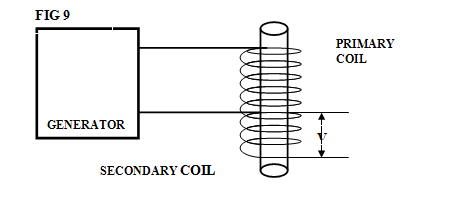
- These eddy currents
- The primary coil
- The generator
- All of the above
7.Which of the following is not a method that may be used to improve the signal-to-noise ratio?
- Change to test frequency that will decrease the noise
- Increase the amplification of the test instrument
- Improve the fill factor
- Add filter circuits to the instruments
8.In eddy current testing, the theoretical maximum testing speed is determined by the:
- Magnetic flux density
- Testing frequency
- Conveyor drive
- Test coil impedance
9.In eddy current testing of ferromagnetic materials, the dc saturating field may be provided by :
- An encircling solenoid
- A magnetic yoke
- Both a and b
- None of the above
10.Which of the following is a property of eddy currents induced in a conductor by an encircling coil?
- The magnitude of eddy current flow is large compared to the current flow in the coil
- The eddy current flow is affected by permeability variation in the samples
- The eddy current flow dissipates no power in the conductor
- None of the above
11.Which of the following is a property of eddy currents induced in a homogeneous conductor by an encircling coil?
- They are weakest on the conductor surface
- The phase of the eddy currents varies through out the conductor
- They travel in straight lines
- They are maximum along the coil axis.
12.Which factor does not affect the phase shift between the transmitted signal and the reflected signal for a reflection type coil(assuming the part is nonferromagnetic)?
- The conductivity of the sample
- The magnitude of the transmitted signal
- The signal of the sample
- The presence of defects in the sample
13.Lift-off certainly reduces the amplitude of the flux leakage signal. The other significant effect it has on the signal is a change in:
- Phase
- Frequency
- Increasing lift-off which reduces the apparent width of the defect
- None of the above
14.The tubular product parameter having the greatest influence on the flux density of the magnetic field in the part (assuming the magnetizing force, H, remains constant)is the :
- Surface roughness of the product
- Diameter of the product
- Wall thickness of the product
- Length of the product
15.Any handling of equipment used in an eddy current system must take into consideration:
- The operator ‘s abilities
- The use of the product being tested
- Speed, frequency of test, sorting speed, and physical control of the product
- All of the above
16.An eddy current system lends itself to quality ratings such as “Quality Number” where the product being inspected:
- Is not defective
- Does not allow defective areas to be removed
- Is of inferior quality
- Has inconsistent quality
17.When inspecting material with eddy currents in an automatic handling system, it is advisable to calibrate and adjust the sensitivity levels to:
- Some electroic source
- Another NDT method
- An NBS standard
- An actual testpart being inspected
18.A distinct advantage of using handling equipment in an eddy current test system is to reduce the error caused by:
- Instrument drift
- Lift-off
- Skin effect
- All of the above
- None of the above
19.Decreased coupling or fill factor results in decreased test sensitivity because:
- Reduced coupling between the driver coil and the specimen induces less eddy current flow in the specimen
- Reduced coupling between the specimen and the pickup coil results in smaller voltages across the pickup coil
- Electrical circuits designed to provide fill factor compensation may prove to be inadequate, depending upon the extent of fill factor loss
- All of the above
20.Why is it desirable to hold the factor or lift-off constant?
- To avoid arcing between the coil and the specimen
- To minimize tester output signal changes that are not relevant to conditions with in the specimen to be tested.
- A fill factor or lift-off change will shift the operating frequency
- To minimize the load on the constant current ac excitation circuits
21.The reactance component is decreased by placing a conducting object in the coil’s electromagnetic field. Why is this so?
- The secondary field is exactly in phase with the primary field
- The secondary field is at precisely 90 degrees with the primary field
- The phase angle between the two field components is always greater than 90 degrees which partially cances the primary field
- The secondary field is 180 degrees out of phase with the primary field which causes a large phase shift
22Test coils may be shielded with conducting material or magnetic material to:
- Shape field
- Increase sensitivity
- Increase resolution
- All of the above
- None of the above
23.When a magnetic bar is placed in the coil’s electromagnetic field,the coil’s reactance is increased. What causes this phenomena?
- The coil becomes magnetic ally saturated
- The permeability raises the inductance of the test coil
- The magnetic test sample’s conductivity increases the reactance value of the coil
- This effect is described mathematically by thr equation B/H=μ
24.When an excitation voltage is applied to a primary winding, only the magnetic flux is in phase and the secondary magnetic flux is minor. When a test object is inserted in this coil, what action takes place?
- The object gets hot and no information is available
- Insertion of the object cancels all information
- The insertion of the test object intensifies the secondary magnetic flux producing a new total magnetic flux which can be used to supply test information
- By subtracting the primary voltage from the secondary voltage, the net voltage is obtained
25.The test coil excitation current should be held constant so that the test piece information obtained by an eddy current system will:
- Contain only flaw information and not indicate variations in magnetic field strength
- Not contain signals generated by cross talk
- Not contain electrical noise
- All of the above
26.Eddy currents flowing in the test object at any depth produce magnetic fields at greater depths, which oppose the primary field, thus breducing its effect and causing what kind of change in current flow as depth increases?
- A decrease
- An increase
- A frequency change
- None of the above
27.Skin effect causes eddy currents to tend to flow near the surface of the test piece. Which of the following factors alter the skin effect?
- Testing frequency
- Test piece temperature
- Test piece hardness
- Test piece permeability
- None of the above
28.Which of the following is not a common undesirable effect to the test caused by the testing environment?
- Temperature variation
- Crack in test sample
- Test object making contact with test coil
- Foreign object in the test coil field
- Test coil vibration
39.There is one function that responds to variations in eddy current flaw and magnetic field conditions. This function actually produces the output signal from the coil. What is this function?
- Phasing
- Resistance
- Reactance
- Impedance
30.The inductive reactance of a test coil, which is one of the most importance impedance quantities, depends upon which of the following?
- Frequency, coil inductance, coil resistance
- Coil inductance only
- Coil resistance and coil inductance only
- Frequency and coil resistance only
- Frequency and coil inductance only
31.An ac current produces eddy currents in a test object. The vector Hp represents the secondary ac field in the test piece. What function occurs to produce a workable test situation? (See figure 10)
- Changes in the test specimen such as a crack, metallurgical and dimensional change alter the secondary field phase and amplitude
- The primary ac current must be 60 cycles to produce this effect
- A temperature raise in the specimen
- A mismatch of the Hp and Hs fields produces a change in the output
32.To separate cracks and diameter effects for steel cylinders, the optimum frequencies correspond to f/fg ratios of less than (see figure 11)
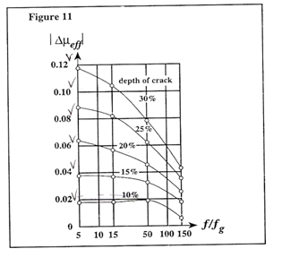
- 10
- 15
- 50
- 100
- 150
33.Thin –walled tubes should be tested for cracks, alloy or wall thickness at frequency ratios between(see Figure 12):
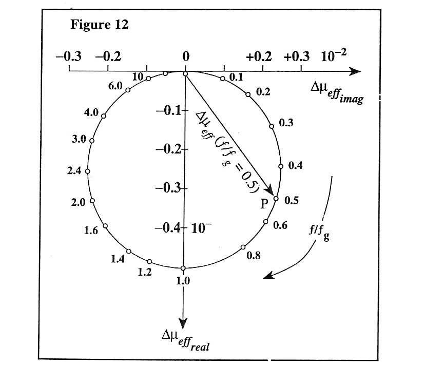
- 0.1 and 0.4
- 0.4 and 2.4
- 2.4 and 4.0
- 4.0 and 10
34.Figure 13 indicates that the largest eddy current indicates from subsurface cracks will occur when the frequency ratio(f/fg) is:
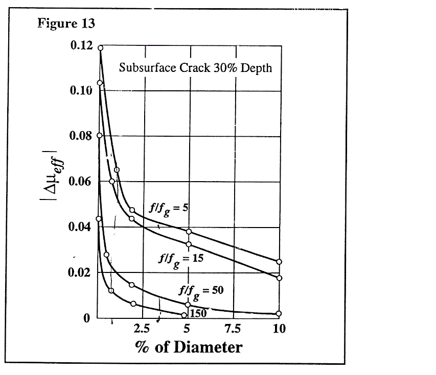
- 5 or less
- 15
- 50
- 150 or more
35.Figure 13 indicates that the magnitude of a signal from a surface crack will increase when the frequency ratio(f/fg):
- Remains the same
- Decreases
- Increases
- None of the above
36.Figure 14 indicates that when inspecting for surface cracks in nonferromagnetic cylinders, the optimum frequency ratio (f/fg) is between :
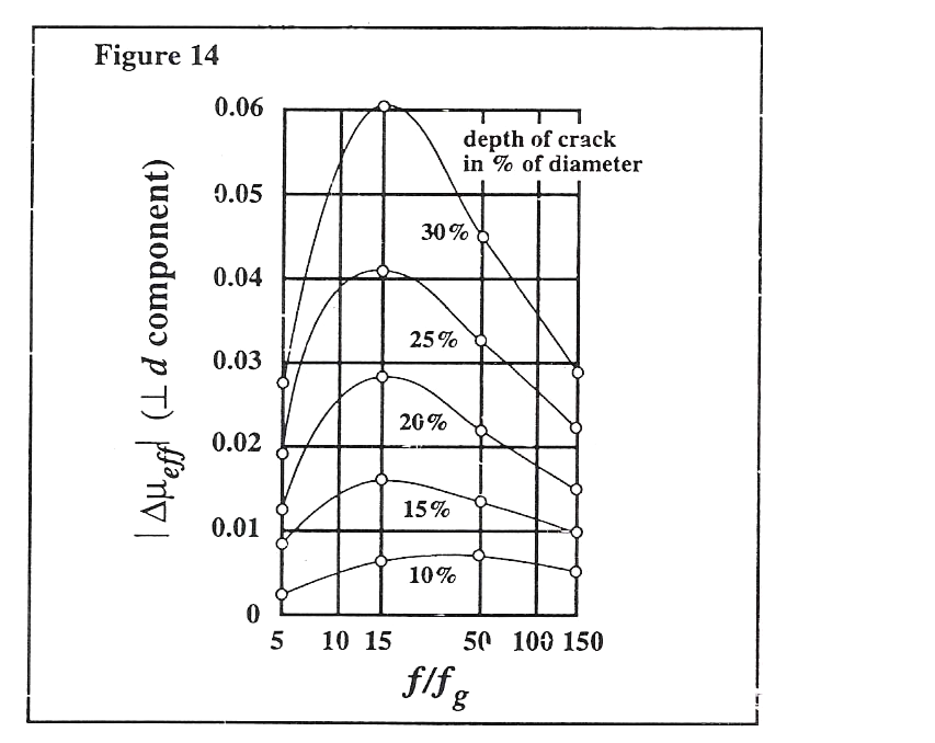
- 5 and 10
- 10 and 50
- 50 and 100
- 100 and 150
37.An operating frequency of 100 khz will have the deepest penetration in:
- Titanium
- Copper
- Stainless steel
- Aluminum
38.As the operating frequency is increased, the impedance of the empty coil:
- Increases
- Decreases
- Remains the same
- None of the above
39.Disadvantage of using a surface probe coil for the inspection of small diameter tubing include:
- Inability to detect small discontinuities
- Slow inspection speed
- Inherent mechanical problem
- Both a and c
- Both b and c
40.Differntial coil system can be of which of the following types? (See figure 15)
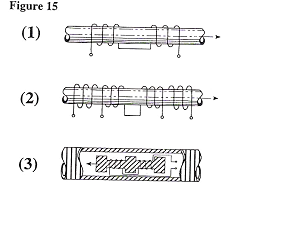
- Sketch no. 1
- Sketch no. 2
- Sketch no. 3
- All of the above
- Both a and b
EDDY CURRENT QB 1
ANSWERS
| Q.NO | ANSWERS | Q.NO | ANSWERS |
| 1 | 2 | 21 | 3 |
| 2 | 1 | 22 | 4 |
| 3 | 4 | 23 | 2 |
| 4 | 1 | 24 | 3 |
| 5 | 3 | 25 | 1 |
| 6 | 4 | 26 | 1 |
| 7 | 2 | 27 | 5 |
| 8 | 2 | 28 | 2 |
| 9 | 3 | 29 | 4 |
| 10 | 2 | 30 | 5 |
| 11 | 2 | 31 | 1 |
| 12 | 2 | 32 | 1 |
| 13 | 2 | 33 | 2 |
| 14 | 3 | 34 | 1 |
| 15 | 4 | 35 | 2 |
| 16 | 2 | 36 | 2 |
| 17 | 4 | 37 | 3 |
| 18 | 2 | 38 | 1 |
| 19 | 4 | 39 | 5 |
| 20 | 2 | 40 | 4 |